
CCNA – Troubleshooting 1
Here you will find answers to Trouble Shooting Questions (Part 1)
Question 1:
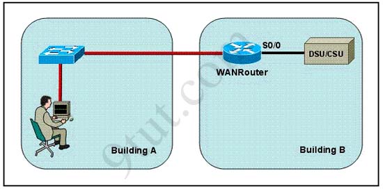
Refer to the exhibit. The network administrator is in a campus building distant from Building B. WANRouter is hosting a newly installed WAN link on interface S0/0. The new link is not functioning and the administrator needs to determine if the correct cable has been attached to the S0/0 interface. How can the administrator accurately verify the correct cable type on S0/0 in the most efficient manner?
A. Telnet to WANRouter and execute the command show interfaces S0/0
B. Telnet to WANRouter and execute the command show processes S0/0
C. Telnet to WANRouter and execute the command show running-configuration
D. Telnet to WANRouter and execute the command show controller S0/0
E. Physically examine the cable between WANRouter S0/0 and the DCE.
F. Establish a console session on WANRouter and execute the command show interfaces S0/0
Answer: D
Explanation:
The show controller command displays the information about the physical interface itself and the type of serial cable plugged into a serial port. In this case, it should be a DTE cable that plugs into a type of data service unit (DSU).
For your understanding, below is the output of this command:
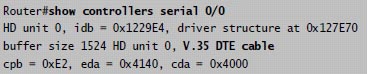
From the output, we notice that serial 0/0 has a DTE cable and would get its clocking from the DSU.
Question 2:
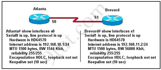
Two routers named Atlanta and Brevard are connected by their serial interfaces as shown in the exhibit, but there is no data connectivity between them. The Atlanta router is known to have a correct configuration. Given the partial configurations shown in the exhibit, what is the problem on the Brevard router that is causing the lack of connectivity?
A. A loopback is not set
B. The IP address is incorrect.
C. The subnet mask is incorrect.
D. The serial line encapsulations are incompatible.
E. The maximum transmission unit (MTU) size is too large.
F. The bandwidth setting is incompatible with the connected interface.
Answer: B
Question 3:
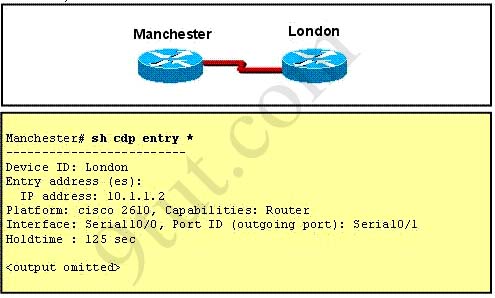
Refer to the exhibit. The two exhibited devices are the only Cisco devices on the network. The serial network between the two devices has a mask of 255.255.255.252. Given the output that is shown, what three statements are true of these devices? (Choose three)
A. The Manchester serial address is 10.1.1.1.
B. The Manchester serial address is 10.1.1.2.
C. The London router is a Cisco 2610.
D. The Manchester router is a Cisco 2610.
E. The CDP information was received on port Serial0/0 of the Manchester router.
F. The CDP information was sent by port Serial0/0 of the London router.
Answer: A C E
Explanation:
From the output, we learn that the IP address of the neighbor router is 10.1.1.2 and the question stated that the subnet mask of the network between two router is 255.255.255.252. Therefore there are only 2 available hosts in this network (22 – 2 = 2). So we can deduce the ip address (of the serial interface) of Manchester router is 10.1.1.1 -> A is correct
The flatform of the neighbor router is cisco 2610, as shown in the output -> C is correct
Maybe the most difficult choice of this question is the answer E or F. Please notice that “Interface” refers to the local port on the local router, in this case it is the port of Manchester router, and “Port ID (outgoing port)” refers to the port on the neighbor router -> E is correct.
Question 4:
A network administrator has configured two switches, named London and Madrid, to use VTP. However, the switches are not sharing VTP messages. Given the command output shown in the graphic, why are these switches not sharing VTP messages?
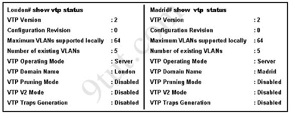
A. The VTP version is not correctly configured.
B. The VTP operating mode is not correctly configured.
C. The VTP domain name is not correctly configured.
D. VTP pruning mode is disabled.
E. VTP V2 mode is disabled.
F. VTP traps generation is disabled.
Answer: C
Explanation
In the exhibit, the Domain Names of 2 switches are mismatched (one is “London” and the other is “Madrid”) so these switches do not share VTP messages -> The VTP domain name is not correctly configured. Notice that the Domain Names should be the same on both switches to share VTP messages.
Question 5:
The network shown in the diagram is experiencing connectivity problems. Which of the following will correct the problems? (Choose two.)
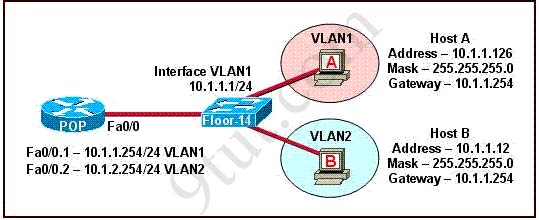
A. Configure the gateway on Host A as 10.1.1.1.
B. Configure the gateway on Host B as 10.1.2.254.
C. Configure the IP address of Host A as 10.1.2.2.
D. Configure the IP address of Host B as 10.1.2.2.
E. Configure the masks on both hosts to be 255.255.255.224.
F. Configure the masks on both hosts to be 255.255.255.240.
Answer: B D
Question 6:
Refer to the exhibit:
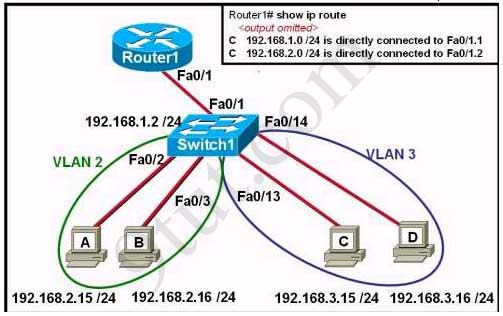
The network administrator has created a new VLAN on Switch1 and added host C and host D. The administrator has properly configured switch interfaces FastEthernet0/13 through FastEthernet0/24 to be members of the new VLAN. However, after the network administrator completed the configuration, host A could communicate with host B, but host A could not communicate with host C or host D. Which commands are required to resolve this problem?
A. Router(config)# interface fastethernet 0/1.3
Router(config-if)# encapsulation dot1q 3
Router(config-if)# ip address 192.168.3.1 255.255.255.0
B. Router(config)# router rip
Router(config-router)# network 192.168.1.0
Router(config-router)# network 192.168.2.0
Router(config-router)# network 192.168.3.0
C. Switch1# vlan database
Switch1(vlan)# vtp v2-mode
Switch1(vlan)# vtp domain cisco
Switch1(vlan)# vtp server
D. Switch1(config)# interface fastethernet 0/1
Switch1(config-if)# switchport mode trunk
Switch1(config-if)# switchport trunk encapsulation isl
Answers: A
Question 7:
Refer to the exhibit. Hosts on the same VLAN can communicate with each other but are unable to communicate with hosts on different VLANs. What is needed to allow communication between VLANs?
A. a switch with a trunk link that is configured between the switches
B. a router with an IP address on the physical interface that is connected to the switch
C. a switch with an access link that is configured between the switches
D. a router with subinterfaces configured on the physical interface that is connected to the switch
Answer: D
Question 8:
The show interfaces serial 0/0 command resulted in the output shown in the graphic. What are possible causes for this interface status? (Choose three)
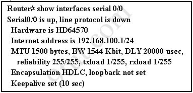
A. The interface is shut down.
B. No keepalive messages are received.
C. The clockrate is not set.
D. No loopback address is set.
E. No cable is attached to the interface.
F. There is a mismatch in the encapsulation type.
Answer: B C F
Question 9:
While troubleshooting a connectivity issue from a PC you obtain the following information:
Local PC IP address: 10.0.0.35/24
Default Gateway: 10.0.0.1
Remote Sever: 10.5.75.250/24
You then conduct the following tests from the local PC:
Ping 127.0.0.1 – Successful
Ping 10.0.0.35 – Successful
Ping 10.0.0.1 – Unsuccessful
Ping 10.5.75.250 – Unsuccessful
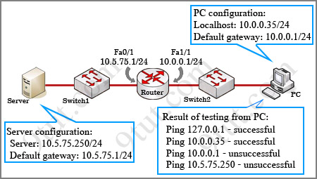
What is the underlying cause of this problem?
A. A remote physical layer problem exists.
B. The host NIC is not functioning.
C. TCP/IP has not been correctly installed on the host.
D. A local physical layer problem exists.
Answer: D


Hi, can u explain question 8 for me, i really don’t understand.
Interface is encapsulated HDLC by default, why choose F?
and why choose B?
Thanks!
I am pretty sure they are referring to the other router on the end of the s0/0 interface. The other router’s protocol might be PtP so you will have a protocol mismatch. That is why F.
Thank say500 for your answer, you was right. Router at the other end may have a different encapsulation protocol like Point-to-Point so it can mismatch with HDLC protocol
We chose answer B because from the output “S0/0 is up, line protocol is down” we can deduce that there is a problem at layer 2 (the Data Link layer) where keepalive messages operate at. And a status like that can be a result of no keepalive messages coming from the remote router
Explanation of Q 8 for those who doesn’t know
B)
Because True encapsulation occurred in layer 2 which is layer 2 and we know that every interface have 2 status ( one is physical which means cable connectivity and second is data link layer which means encapsulation like hdlc, ppp, frame relay, etc etc.
C)
If clock rate is not set then no bandwidth will available for communication so that’s why C is correct.
D)
Check the explanation of B)
wrong encapsulation is make “line protocol is down” :)
bcoz in q.8 the answer a is incorrect it can be if interface line protocol is administratively shut down state
The output says Serial 0/0 is up,line protocol is down .So,we know that the first aspect that is Serial 0/0 is refering to the Physical layer,which infact is up so there seems to be no problem with the Physical layer or the cabling ,So we eliminate the the options A) and E)
Second aspect suggests that the line protocol is down ,which means that there is a problem with the Data link layer Most possible problems with the datalink layer are 1) Wrong encapsulation 2) wrong clock rate so we select C) & F) & now we are left with B) and D) Keepalive timer is essential for each end to know if the other end disappears, If there is no activity on the connection for 10secs , the end device sends a probe segment to the router so my assumption is that no Keepalive messages were received before the timer expired.
my answer is B C F
please give me a correct answer for this
what is the advantage of using point to point sub interface instead of a multipoint interface in router ?
By using point to point sub interface you can avoid split horizon on Frame Relay circuits
While troubleshooting a connectivity issue from a PC you obtain the following
information:
Local PC IP address: 190.0.3.35/24
Default Gateway: 190.0.3.1
Remote Server: 190.0.5.250/24
You then conduct the following tests from the local PC:
Ping 127.0.0.1 – Unsuccessful
Ping 190.0.3.35 – Successful
Ping 190.0.3.1 – Unsuccessful
Ping 190.0.5.250 – Unsuccessful
What is the underlying cause of this problem?
A. TCP/IP not correctly installed
B. Local physical layer problem
C. NIC not functioning
D. Remote physical layer problem
E. None of the above
Answer: A
Explanation:
Every Windows based PC uses the 127.0.0.1 as the local loopback IP address. Every PC
will respond to this local IP address if the TCP/IP stack is correctly installed and running
on the machine. If you cannot ping the loopback address of 127.0.0.1, then something is
wrong with the TCP/IP protocol stack.
is this answer correct?
is this a local physical layer problem?
9tut plz answer very urgent
Blaze, you mistyped the question because if you can not ping 127.0.0.1 (Ping 127.0.0.1 – Unsuccessful) then you can not ping 190.0.3.35 successfully (but you wrote Ping 190.0.3.35 – Successful)
If you can ping 190.0.3.35 then its TCP/IP protocol was installed correctly, so the answer can not be A
then the answer is “Local physical layer problem” right?
Yes!
I really want to know the reason why “D” is selected as the correct answer. in the Q1.
The answer is simply “A”, isn’ t it ?
why is “the controller S0/0″ here?
@Shin: I updated the page with the explanation you need. In short, the “show interfaces s0/0″ command doesn’t give us information about the cable type
Why there’s local physical problem on the question 9?
What if link between Router and Switch1 is failed? Thanks!
Does the ‘local’ in this case refer to what’s behind the router meaning broadcast domain where the host is located? Thanks
@Vaidas: Yes, the “local” here means “on the same network” or “in a same broadcast domain”
question 9
how can the answer B correct?
it can ping both 127.0.0.1 and its ip address, it means NIC is functioning and cable is connected to PC and it’s getting the IP address so there absolutely no local physical layer problems……the problem is with a remote physical layer.
The “local physical layer” here is the interface fa1/1 of the router, not the PC itself. The word “local” here means “in the same broadcast domain”
well I would say that the question itself is incorrect. I myself understood this question as a local host vs remote host. This is what unclear in this question. “local physical layer” for me is local PC physical layer……and “remote physical layer” – remote switches and routers. That’s why I was shocked when I saw the answer.
Be careful answering this question.
Hi 9UT,
I can see the confusion with question 9, maybe if it was laid out in ref to the router rather than the PC, then we may of got your drift.
Anyway THANK YOU VERY MUCH for putting together an awesome site..
Please can somebody explain question 2 as i thought it was
F. The bandwidth setting is incompatible with the connected interface.
As the Bw are different on each router ?
Two connected interfaces don’t belong to one network, so it is the problem. The BW will not cause the lack of connectivity
Q#6 Host B hast incorrect ip address, Must be 192.168.2.16 instead of ~2.15/24 because it’s HOST A’s ip address…but we have understood
TUT9 — Thanks for posting that about question 9 being very misleading. I too reasoned that, 1)if you can ping the loopback on the PC, then no physical problem (TCP/IP can be wrong and the loopback will still respond unless the NIC is bad). 2)If the PC can ping it’s own IP, then the protocol stack is working and configured correctly. Therefore, this points to a “remote” problem. BUT HERE’s the catch, “local” means on the subnet and includes the router interface (which does not respond to a ping). Cisco incorrectly uses the term “local” here, and most experienced IT pros like me, would consider “local” to mean the PC (that is the correct term whether you are MCSE like me, or network geek) and that makes the question is poorly worded. THE PINGs point to a problem with the gateway, not the PC, but the gateway is “local” so the answer listed is correct for number 9. WATCH OUT FOR that one!
Hi,
Regarding question 3, I tried with packet tracer…
Manchester#sh ip int br
Interface IP-Address OK? Method Status Protocol
Serial0/0/0 10.1.1.1 YES manual up up
Manchester#sh cdp entry *
Device ID: London
Entry address(es):
IP address : 10.1.1.2
Platform: cisco C1841, Capabilities: Router
Interface: Serial0/0/0, Port ID (outgoing port): Serial0/0/1
Holdtime: 124
So answer E is correct.
re:
Hi, can u explain question 8 for me, i really don’t understand.
Interface is encapsulated HDLC by default, why choose F?
and why choose B?
Thanks!
i think it is because, your line protocol is down so maybe cuz of a worng encapsulation . (other side has different encapsulation)
Hi!
If you noticed in the output, it said serial UP and line protocol DOWN.
This part means: serial > Layer 1 , line protocol > configuration on the router
With this information you will discard option A: The interface is shut down, because the interface is layer 1 and it is UP. Also, option E: No cable is attached to the interface, it is Layer 1.
Option D: No loopback address is set, could not be related.
Now we have the following 3 options for the question What are possible causes for this interface status?:
B. No keepalive messages are received > because the link is down.
C. The clockrate is not set > If clockrate is not configured it could produce the link to be down
F. There is a mismatch in the encapsulation type > both end points must have the same encapsulation type, so they will be able to understand each other.
About your question, you are correct by default the encapsulation type is HDLC, the other types are frame relay and ppp.
hi 9tut,
may i please know the explanation for the q.no4.
(Is it possible to have two server in the same a network as you configured.)
They are two switches that have assigned domain incorrectly (one is London and another is Madrid) so they can not communicate with each other.
Which is the correct answer on Question 9? Is C or D?
p4s 7.73 correct answer is C.
please reply for those who taken the exam..
Thanks
The answer to Q9 is correct (D) that’s because a ping to the local network (address 10.0.0.1) was unsuccessful.
A ping to the loopback address 127.0.0.1 was successful meaning that TCP/IP stack was correctly configured. and hence answer “C” is incorrect.
One of the questions I had when I took my exam, I was not able to find anywhere.
A router receives a packet with a destination address of 10.0.5.65. Which interface will the router forward the packet to:
4 interfaces – Directly connected
10.0.5.0 /24 – Fa0/0 via ********
10.0.5.64 /27 – Fa0/1 via ********
10.0.5.64 /28 – S0/0 via ********
10.0.5.64 /29 – s0/1 via ********
a. Fa0/0
b. Fa0/1
c. s0/0
d. s0/1
I had absolutely no idea………….
Hi BD
The correct answer is s0/1 because the subnets mask is 29. You must to think in binary. With 29 you have 5 bit of coincidence for number (65) for that reason the match is more hight than others ….
Look
0 1 0 0 0 /29 here you have 5 bits of coincidence
0 1 0 0 /28 here you have only 4 bits of coincidence
0 1 0 /27 here you have only 3 bits of coincidence
Did you understand?
i couldnt understand the answer for question 6,anybody plz makes me understand?ur help will be great for me.
@bhagwan
For question #6, as shown in the results of using “show ip route command”, you can see that the connection to the 192.168.3.0 network is missing. 192.168.3.0/24 includes Host C and D in VLAN 3.
Basically, a sub-interface for 192.168.3.0/24 is needed in order to have Inter-VLAN communication. Thus, VLAN 2 and VLAN 3 will be able to communicate.
Question 4.
The answer is the domain names don’t match. This makes sense. But, isn’t the fact they’re both in “Server” mode also mean that they wont exchange info?
Dear 9tut, I have a simple question which looks critical to me.
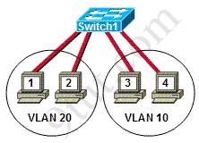
When Hub cannot read data or understand IP address, if I connect 4 PCs to my hub where PC A and B with 10.1.1.1 and 10.1.1.2 as their IPs; and PC C & PC D with 11.1.1.1 and 11.1.1.2 as their IPs, when I send a packet from 10.1.1.1 PC A to 11.1.1.1 PC C, why is it not sending? Hub should broadcast right? Can you please clear this doubt at the earliest of your convenience? I believe you are going great in helping CCNA aspirants and even higher level folks.
@ Ramakrishna,
PC’s A & C are on different networks so PC A will send packet to its Default Gateway address not address of PC C. If no Default Gateway device attached to hub all devices will ignore the packet because it doesn’t match their own address.
Hope this helps.
@Ramakrishna,
Regarding last post.
Sorry, I meant Layer 2 address not layer 3( frames not packets ), so PC A broadcasts arp for default gateway. no default gateway = no arp match. ( need layer 3 device to ROUTE between LAN’s )
Hope this is clearer.
Hi,
Workstation A has been assigned an IP address of 192.0.2.24/28. Workstation B has been assigned an IP address of 192.0.2.100/28. The two Workstations are connected with a straight-through cable. Attempts to pin between the hosts are unsuccessful. What two things can be done to allow communications between the hosts?
a) Replace the straight-through cable with a crossover cable
b) change the subnet mask of the hosts to /25
c) Change the subnet mask of the hosts to /26
d) change the address of Workstation A to 192.0.2.15
e) change the address of Workstation B to 192.0.2.111
ans:- a and b
can any1 explain how come by change the subnet mask from /28 to /25 will solve the problem?
regards,
Hi Jack,
Explanation for answer.
For connecting similar devices we need a cross-over cable.
In this question both the devices are PC’s so we require a Cross-Over cable.
This is how Ans A is right.
If you see the IP address , subnet mask is 255.255.255.240 right so the PC A lies in second subnet which is 192.0.2.16 means 16-32 where 16 is the network .
For PC B it’s IP address is 192.0.2.100/28 so this comes under 192.0.2.96 network.
For hosts to communicate with each other needs a Layer 2 or 3 device or should be in same subnet while connecting directly.
If you put both the PC’s in /25 Subnet Mask, ip address range is 0 to 127 , thus 192.0.2.24 and 192.0.2.100 comes in same subnet
This is how Ans B is right.
Hope would have been useful.
If you find any mistakes , please rectify it.
regards,
Hi all !
Can anyone explain is answer right?
Examine the following diagram carefully , the switch was not selected as root bridge vlan 1, why?
show spanning-tree vlan 1
vlan0001
spanning tree enabled protocol rstp
root id prio 20481
address 0008.217a.5800
cost 38
port 1 (fa0/1)
hello time 2 sec max age 2 sec forward delay 15 sec
Bridge Id priority 32769( priority 32768 sys- id -ext 1
address 0008.205e.6600
hello time 2 sec max age 2 sec forward delay 15 sec
aging time 300
interface Role stats cost prio.nbr type
fa0/1 root fwd 19 128.1 p2p
fa0/4 desg fwd 38 128.1 p2p
fa0/11 altn Blk 57 128.1 p2p
fa0/13 desg fwd 38 128.1 p2p
A.Its Mac address is higher than the elected root bridge
B.It has multiple interfaces connected to root network segment
C. It is implementing RSTP while the elected root bridge is running 802.1d spanning tree
D. It has higher bridge Id Than the elected rootbridge
Answer is D
My explanation:
BID = bridge priority + Mac address
swith 1:
top 1 : currentone
BID = 20481 + 0008.217a.5800
switch 2:
secondly displayed alredy existed switch
BID = 32769 +0008.205e.6600
Switch 2′s BID > switch’s 1 BID
By this, I thing switch 2 is the root bridge.
Do we need to thing, other factors? i.e cost, etc..
Please clear.
thank you in advance.
Hi all!
My concept was wrong before. that is my mistake, sorry.
By that switch 2 should not be anymore rootbridge, newer one- top 1- should be root bridge. because of lower bridge ID.
by that can we conclude, if priority is not same then lesser priority automatically becomes the root bridge, regardless of MAC addresses ?
‘switch was not selected as root bridge’ – which is confused me.. maybe they may add ‘ anymore’ at the end. By that I know examiner talk about already existing one.
Thank you
Notice: The day of the above posts are not correct because of the upgrade
i got my exam yesterday and passed with 974. especial thanks for the 9tut. pass4sure & testinside dumps are still valid. sims are eigrp,vtp & access-list only the ip addresses are changed. in access-list the the pc also changed. again thanks for the 9tut and all of the contributors
if any one need help from me pls email to
hasy_001@yahoo.com
can any one give the explanation for question 6 why the answer is option “A”
hi can u plz explain y its option d in ques 5….
@lakshman
In order for inter VLAN communication to take place, the router must be configured with subinterfaces each with its own unique subnet per VLAN.
If we base this information on the answer’s provided option A has the correct commands to configure the router with a 3rd (fa0/1.3) subinterface with IP 192.168.3.1.
After this subinterface has been configured with the correct encapsulation type, Hosts A&B on VLAN 2 will be able to communicate with hosts C&D on VLAN 3.
Hope that helps :)
@AT
The IP for Host B is 10.1.1.12. If you look at the information provided for the subinterfaces on Router POP, VLAN 2 is on subnet 10.1.2.254. Host B is suppose to be on VLAN 2 but is configured with an incorrect IP address. If host B were to be configured with 10.1.2.2 (option D) this would correct the issue because now host B is on the same subnet as its gateway.