
New CCNA – Frame Relay
Note: If you are not sure about Frame Relay, please read our Frame Relay Tutorial.
Question 1
The output of the show frame-relay pvc command shows ”PVC STATUS=INACTIVE”. What does this mean?
A. The PVC is configured correctly and is operating normally,but no data packets have been detected for more than five minutes.
B. The PVC is configured correctly, is operating normally and is no longer actively seeking the address the remote route.
C. The PVC is configured correctly, is operating normally and is waiting for interesting to trigger a call to the remote router.
D. The PVC is configured correctly on the local switch, but there is a problem on the remote end of the PVC.
E. The PVC is not configured on the switch.
Answer: D
Explanation
The PVC STATUS displays the status of the PVC. The DCE device creates and sends the report to the DTE devices. There are 4 statuses:
+ ACTIVE: the PVC is operational and can transmit data
+ INACTIVE: the connection from the local router to the switch is working, but the connection to the remote router is not available
+ DELETED: the PVC is not present and no LMI information is being received from the Frame Relay switch
+ STATIC: the Local Management Interface (LMI) mechanism on the interface is disabled (by using the “no keepalive” command). This status is rarely seen so it is ignored in some books.
Question 2
Which command allows you to verify the encapsulation type (CISCO or IETF) for a frame relay link?
A. show frame-relay map
B. show frame-relay lmi
C. show inter serial
D. show frame-relay pvc
Answer: A
Explanation
The “show frame-relay map” command displays the current map entries and information about the connections, including encapsulation type.
You can check Table 33 in the following link: http://www.cisco.com/en/US/docs/ios/12_2/wan/command/reference/wrffr4.html#wp1029343
It clearly states there is a Field which can be Cisco or IETF, which “indicates the encapsulation type for this map”. We quote that Table 33 here for your quick reference (you will see what we want to imply in bold):
| Field | Description |
| Serial 1 (administratively down) | Identifies a Frame Relay interface and its status (up or down). |
| ip 131.108.177.177 | Destination IP address. |
| dlci 177 (0xB1,0x2C10) | DLCI that identifies the logical connection being used to reach this interface. This value is displayed in three ways: its decimal value (177), its hexadecimal value (0xB1), and its value as it would appear on the wire (0x2C10). |
| static | Indicates whether this is a static or dynamic entry. |
| CISCO | Indicates the encapsulation type for this map; either CISCO or IETF. |
| TCP/IP Header Compression (inherited), passive (inherited) | Indicates whether the TCP/IP header compression characteristics were inherited from the interface or were explicitly configured for the IP map. |
The “show frame-relay lmi” gives us information about the LMI encapsulation type used by the Frame Relay interface, which can be ANSI, CISCO or Q933a. Therefore it is not what the question requires (CISCO or IETF).
Question 3
Refer to the exhibit. Which statement describes DLCI 17?
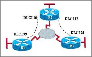
A: DLCI 17 describes the ISDN circuit between R2 and R3.
B: DLCI 17 describes a PVC on R2. It cannot be used on R3 or R1.
C: DLCI 17 is the Layer 2 address used by R2 to describe a PVC to R3.
D: DLCI 17 describes the dial-up circuit from R2 and R3 to the service provider.
Answer: C
Explanation
DLCI stands for Data Link Connection Identifier. DLCI values are used on Frame Relay interfaces to distinguish between different virtual circuits. DLCIs have local significance because the identifier references the point between the local router and the local Frame Relay switch to which the DLCI is connected.
Question 4
Users have been complaining that their Frame Relay connection to the corporate site is very slow. The network administrator suspects that the link is overloaded. Based on the partial output of the Router#show frame relay pvc command shown in the graphic, which output value indicates to the local router that traffic sent to the corporate site is experiencing congestion?

A. DLCI=100
B. last time PVC status changed 00:25:40
C. in BECN packets 192
D. in FECN packets 147
E. in DF packets 0
Answer: C
Explanation
First we should grasp the concept of BECN & FECN through an example:
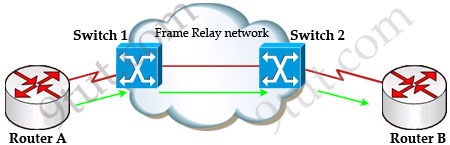
Suppose Router A wants to send data to Router B through a Frame Relay network. If the network is congested, Switch 1 (a DCE device) will set the FECN bit value of that frame to 1, indicating that frame experienced congestion in the path from source to destination. This frame is forwarded to Switch 2 and to Router B (with the FECN bit = 1).
Switch 1 knows that the network is congesting so it also sends frames back to Router A with BECN bit set to 1 to inform that path through the network is congested.
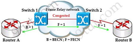
In general, BECN is used on frames traveling away from the congested area to warn source devices that congestion has occurred on that path while FECN is used to alert receiving devices if the frame experiences congestion.
BECN also informs the transmitting devices to slow down the traffic a bit until the network returns to normal state.
The question asks “which output value indicates to the local router that traffic sent to the corporate site is experiencing congestion” which means it asks about the returned parameter which indicates congestion -> BECN.
Question 5
What occurs on a Frame Relay network when the CIR is exceeded?
A. All TCP traffic is marked discard eligible.
B. All UDP traffic is marked discard eligible and a BECN is sent.
C. All TCP traffic is marked discard eligible and a BECN is sent.
D. All traffic exceeding the CIR is marked discard eligible.
Answer: D
Explanation
Committed information rate (CIR): The minimum guaranteed data transfer rate agreed to by the Frame Relay switch. Frames that are sent in excess of the CIR are marked as discard eligible (DE) which means they can be dropped if the congestion occurs within the Frame Relay network.
Note: In the Frame Relay frame format, there is a bit called Discard eligible (DE) bit that is used to identify frames that are first to be dropped when the CIR is exceeded.
Question 6
What command is used to verify the DLCI destination address in a Frame Relay static configuration?
A show frame-relay pvc
B. show frame-relay lmi
C. show frame-relay map
D. show frame relay end-to-end
Answer: C
Question 7
|
Router 1# show running-config interface serial0/0 |

As a technician, you found the router1 is unable to reach the second router. Both routers are running IOS version 12.0.
Based on this information, what is the most likely cause of the problem?
A. incorrect IP address
B. incorrect bandwidth configuration
C. incorrect map statement
D. incorrect LMI configuration
Answer: C (In fact none is correct)
Explanation
First we have to say this is an unclear question and it is wrong. The “frame-relay map ip” statement is correct thus none of the four answers above is correct. But we guess there is a typo in the output. Maybe the “ip address 172.16.100.2 255.255.0.0″ command should be “ip address 172.16.100.1 255.255.0.0″. That makes answer C correct.
Question 8
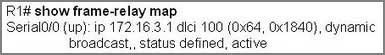
Refer to the exhibit. What is the meaning of the term dynamic as displayed in the output of the show frame-relay map command shown?
A. The Serial0/0 interface is passing traffic.
B. The DLCI 100 was dynamically allocated by the router
C. The Serial0/0 interface acquired the IP address of 172.16.3.1 from a DHCP server
D. The DLCI 100 will be dynamically changed as required to adapt to changes in the Frame Relay cloud
E. The mapping between DLCI 100 and the end station IP address 172.16.3.1 was learned through Inverse ARP
Answer: E
Explanation
The term dynamic indicates that the DLCI number and the remote router IP address 172.16.3.1 are learned via the Inverse ARP process.
Inverse ARP is a technique by which dynamic mappings are constructed in a network, allowing a device such as a router to locate the logical network address and associate it with a permanent virtual circuit (PVC).
Question 9
Refer to the exhibit. Which WAN protocol is being used?

A. ATM
B. HDLC
C. Frame Relay
D. PPP
Answer: C
Explanation
Local Management Interface (LMI) is a signaling standard protocol used between your router (DTE) and the first Frame Relay switch. From the output we learn this interface is sending and receiving LMI messages -> Frame Relay is being used.
Question 10
The command frame-relay map ip 10.121.16.8 102 broadcast was entered on the router. Which of the following statements is true concerning this command?
A. This command should be executed from the global configuration mode.
B. The IP address 10.121.16.8 is the local router port used to forward data.
C. 102 is the remote DLCI that will receive the information.
D. This command is required for all Frame Relay configurations.
E. The broadcast option allows packets, such as RIP updates, to be forwarded across the PVC.
Answer: E
Explanation
The command frame-relay map ip 10.121.16.8 102 broadcast means to mapping the distal IP 10.121.16.8 102to the local DLCI 102. When the “broadcast” keyword is included, it turns Frame Relay network as a broadcast network, which can forward broadcasts.


Q2 = C
Please fix this question, because its completly wrong answer !
exemple:
Router#show frame-relay map
Serial1/2 (up): ip 172.16.1.4 dlci 401(0×191,0×6410), dynamic,
broadcast,, status defined, active
Serial1/2 (up): ip 172.16.1.5 dlci 501(0x1F5,0x7C50), dynamic,
broadcast,, status defined, active
Serial1/2 (up): ip 172.16.1.2 dlci 301(0x12D,0x48D0), dynamic,
broadcast,, status defined, active
—————-
—————-
http://www.ciscopress.com/articles/article.asp?p=170741&seqNum=9
show interface serial interface-type number
The show interface serial privileged EXEC mode command displays detailed information of a physical interface or a subinterface. The information shown by the show interface serial command offers the following information on Frame Relay:
The type of Frame Relay encapsulation used on an interface or PVC
The keepalive interval configured
The Frame Relay LMI type used
The status of Frame Relay LMI
Information on whether the interface is configured as a Frame Relay DTE or a DCE device
Example 4-30 shows a sample output of the show interface serial command. Different hardware interface types might have slightly different output formats.
Example 4-30 Sample Output of show interface serial Command
Router#show interface serial1/2
Serial1/2 is up, line protocol is up
Hardware is CD2430 in sync mode
Internet address is 172.16.1.1/24
MTU 1500 bytes, BW 128 Kbit, DLY 20000 usec,
reliability 255/255, txload 1/255, rxload 1/255
Encapsulation FRAME-RELAY, loopback not set
Keepalive set (10 sec)
LMI enq sent 131, LMI stat recvd 116, LMI upd recvd 0, DTE LMI up
LMI enq recvd 0, LMI stat sent 0, LMI upd sent 0
LMI DLCI 1023 LMI type is CISCO frame relay DTE
FR SVC disabled, LAPF state down
Broadcast queue 0/64, broadcasts sent/dropped 9/0, interface broadcasts 0
Last input 00:00:03, output 00:00:03, output hang never
Last clearing of “show interface” counters 00:24:10
Input queue: 0/75/0/0 (size/max/drops/flushes); Total output drops: 0
Queueing strategy: fifo
Output queue :0/40 (size/max)
5 minute input rate 0 bits/sec, 0 packets/sec
5 minute output rate 0 bits/sec, 0 packets/sec
241 packets input, 8933 bytes, 0 no buffer
Received 0 broadcasts, 0 runts, 0 giants, 0 throttles
0 input errors, 0 CRC, 0 frame, 0 overrun, 0 ignored, 0 abort
164 packets output, 2865 bytes, 0 underruns
0 output errors, 0 collisions, 10 interface resets
0 output buffer failures, 0 output buffers swapped out
2 carrier transitions
DCD=up DSR=up DTR=up RTS=up CTS=up
Q2 is another trick question:
Answer: A is correct, because the encapsulation shows only with sh frame-relay map command instead of sh int serial.
Please check my lab below, the question is asking for the frame-relay encapsulation, not the LMI type as some people are writing here.
In this Lap below, encapsulation is IETF and LMI type is CISCO.
R1#show frame-relay map
Serial0/0/0 (up): ip 201.2.2.2 dlci 100, dynamic, broadcast, IETF, status defined, active
Many people confuses LMI type with Frame relay encapsulation.
R1#sh int s0/0/0
Serial0/0/0 is up, line protocol is up (connected)
Hardware is HD64570
Internet address is 201.2.2.1/30
MTU 1500 bytes, BW 64 Kbit, DLY 20000 usec,
reliability 255/255, txload 1/255, rxload 1/255
Encapsulation Frame Relay, loopback not set, keepalive set (10 sec)
LMI enq sent 39, LMI stat recvd 39, LMI upd recvd 0, DTE LMI up
LMI enq recvd 0, LMI stat sent 0, LMI upd sent 0
LMI DLCI 1023 LMI type is CISCO frame relay DTE
Broadcast queue 0/64, broadcasts sent/dropped 0/0, interface broadcasts 0
Last input never, output never, output hang never
Last clearing of “show interface” counters never
Input queue: 0/75/0 (size/max/drops); Total output drops: 0
Queueing strategy: weighted fair
Output queue: 0/1000/64/0 (size/max total/threshold/drops)
Conversations 0/0/256 (active/max active/max total)
Reserved Conversations 0/0 (allocated/max allocated)
Available Bandwidth 48 kilobits/sec
5 minute input rate 0 bits/sec, 0 packets/sec
5 minute output rate 0 bits/sec, 0 packets/sec
0 packets input, 0 bytes, 0 no buffer
Received 0 broadcasts, 0 runts, 0 giants, 0 throttles
0 input errors, 0 CRC, 0 frame, 0 overrun, 0 ignored, 0 abort
0 packets output, 0 bytes, 0 underruns
0 output errors, 0 collisions, 1 interface resets
0 output buffer failures, 0 output buffers swapped out
0 carrier transitions
DCD=up DSR=up DTR=up RTS=up CTS=up
Sh run command:
!
interface Serial0/0/0
bandwidth 64
ip address 201.2.2.1 255.255.255.252
encapsulation frame-relay ietf
frame-relay interface-dlci 100
clock rate 64000
Q7 – 9Tut copy the question with wrong DLCi number, that´s it because all of us are confusing with this.
Yes, the answer is correct answer, but the Question is wrong, DLCI should be 200 like cisco exam.
Please check below:
https://learningnetwork.cisco.com/thread/13427
Think of the PVC as a pipe with 2 ends. (that part is not so hard to imagine. It is called a PVC after all. )
Imagine that you are at one end of the pipe, and I am at the other. The label or DLCI the provider has given me for my end of the pipe is 22. The label the provider has given to your end of the pipe is 33. My IP address is 10.0.0.22. Your IP address is 10.0.0.33. For you to send a packet to me (destined for 10.0.0.22), you would need to send the frame on the PVC that goes to me. The PVC that goes to me is the one with your local DLCI of 33.
Think of the DLCI number as a freeway on-ramp. That is all it is.
The frame map on your router would be:
frame map ip 10.0.0.22 33 broadcast (using your DLCI 33 as an onramp to reach me at 10.0.0.22)
The frame map on my router would be
frame map ip 10.0.0.33 22 broadcast (using my DLCI 22 as an onramp to reach you at 10.0.0.33)
Best wishes,
Keith
Q2, 7, 9 in my exam today. Passed
Q7 witch error on DLCI number
frame-relay map ip 172.16.100.1 200 broadcast instead of
frame-relay map ip 172.16.100.1 100 broadcast
Q3 & Q5 in my exam today.
2, 7 , 9 today. Praise allah for i have passed
frame relay was too old why until now but in exam
and are they use frame relay in lab exam>???
Q3, 5 today
With regards to Q2, the answer of ‘show frame-relay map’ is correct, but I see no one has really explained why that is.
The show frame map command will show the frame-relay encap ONLY on the main interface when the main interface is configured. The show frame map command when used on a subinterface for say point-to-point will NOT show the encap type. So, if you’re using subinterfaces, the encap will default to CISCO unless otherwise configured.
Q2, Q7, Q9 On 15th Feb.
Q2, Q9
q3,5,8
Marcelo is absolutely right ,
Q-2 there is nothing wrong in question-2
Only “show frame-relay map” command shows the frame-relay encapsulation type ( cisco / ietf)
“show interface seriial” command just gives you what kind of encapsulation you are using – HDLC , ARPA , PPP or Frame relay
Q2 is correct.
“show inter serial” is an incomplete command. Get a router, Try it exact word for word.
LMI is not encapsulation.
No devils advocate. Yes Show interfaces serial x/x will give you encap, however (same as cisco routing rules) the closest match for the answer is “show frame-relay map” because the question asks for encapsulation on, “a frame relay link” and not on an interface.
Q4 and Q10 on exam today
Q1,3
I believe Bryce is correct . because you can get frame encapsulation with both commands (sh int s0/0 and sh frame-relay map). But Sh int s0/0 is showing output only for s0/0 and also command listed in answers is not complete command
Q2,6
lmi is signaling protocol, you can configure with: frame-relay lmi-tye { ansi / cisco / q933a }
you can see with:
show frame-relay lmi
LMI Statistics for interface Serial0/3/0 (Frame Relay DTE) LMI TYPE = CISCO <<<===
encapsulation frame-relay is cisco or ietf
you can configuring:
R2(config-if)#frame-relay map ip 192.168.0.3 200 broadcast { cisco / ietf} ?
cisco Use CISCO Encapsulation
ietf Use RFC1490/RFC2427 Encapsulation
you can see:
R2#show frame-relay map
Serial0/3/0 (up): ip 192.168.0.3 dlci 200, static,
broadcast,
== >> CISCO, status defined, active
If I read only 9tut…will ill be able to pass