Building a working network is important but monitoring its health is as important as building it. Luckily we have tools to make administrator’s life easier and SNMP is one among of them. SNMP presents in most of the network regardless of the size of that network. And understanding how SNMP works is really important and that what we will learn in this tutorial.
Understand SNMP
SNMP consists of 3 items:
+ SNMP Manager (sometimes called Network Management System – NMS): a software runs on the device of the network administrator (in most case, a computer) to monitor the network.
+ SNMP Agent: a software runs on network devices that we want to monitor (router, switch, server…)
+ Management Information Base (MIB): is the collection of managed objects. This components makes sure that the data exchange between the manager and the agent remains structured. In other words, MIB contains a set of questions that the SNMP Manager can ask the Agent (and the Agent can understand them). MIB is commonly shared between the Agent and Manager.

READ MORE…
As an administrator of a network, you have just completed all the configuration and they are working nicely. Now maybe the next thing you want to do is to set up something that can alert you when something goes wrong or down in your network. Syslog is an excellent tool for system monitoring and is almost always included in your distribution.
Places to store and display syslog messages
There are some places we can send syslog messages to:
| Place to store syslog messages |
Command to use |
| Internal buffer (inside a switch or router) |
logging buffered [size] |
| Syslog server |
logging |
| Flash memory |
logging file flash:filename |
| Nonconsole terminal (VTY connection…) |
terminal monitor |
| Console line |
logging console |
Note: If sent to a syslog server, messages are sent on UDP port 514.
By default, Cisco routers and switches send log messages to the console. We should use a syslog server to contain our logging messages with the logging command. Syslog server is the most popular place to store logging messages and administrators can easily monitor the wealth of their networks based on the received information.
READ MORE…
The main disadvantage of HSRP and VRRP is that only one gateway is elected to be the active gateway and used to forward traffic whilst the rest are unused until the active one fails. Gateway Load Balancing Protocol (GLBP) is a Cisco proprietary protocol and performs the similar function to HSRP and VRRP but it supports load balancing among members in a GLBP group. In this tutorial, we will learn how GLBP works.
| Note: Although we can partially configure load balancing via HSRP or VRRP using multiple groups but we have to assign different default gateways on the hosts. If one group fails, we must reconfigure the default gateways on the hosts, which results in extra administrative burden. |
GLBP Election
When the routers are configured to a GLBP group, they first elect one gateway to be the Active Virtual Gateway (AVG) for that group. The election is based on the priority of each gateway (highest priority wins). If all of them have the same priority then the gateway with the highest real IP address becomes the AVG. The AVG, in turn, assigns a virtual MAC address to each member of the GLBP group. Each gateway which is assigned a virtual MAC address is called Active Virtual Forwarder (AVF). A GLBP group only has a maximum of four AVFs. If there are more than 4 gateways in a GLBP group then the rest will become Standby Virtual Forwarder (SVF) which will take the place of a AVF in case of failure. The virtual MAC address in GLBP is 0007.b400.xxyy where xx is the GLBP group number and yy is the different number of each gateway (01, 02, 03…).
Note:
+ In this tutorial, the words “gateway” and “router” are use interchangeable. In fact, GLBP can run on both router and switch so the word “gateway”, which can represent for both router and switch, is better to describe GLBP.
+ For switch, GLBP is supported only on Cisco 4500 and 6500 series. |
The gateway with the highest priority among the remaining ones is elected the Standby AVG (SVG) which will take the role of the AVG in the case it is down.
READ MORE…
EtherChannel is the technology which is used to combine several physical links between switches or routers into one logical connection and treat them as a single link. Let’s take an example to see the benefits of this technology:
Suppose your company has two switches connecting with each other via a FastEthernet link (100Mbps):

Your company is growing and you need to transfer more than 100 Mbps between these switches. If you only connect other links between the two switches it will not work because Spanning-tree protocol (STP) will block redundant links to prevent a loop:

To extend the capacity of the link you have two ways:
+ Buy two 1000Mbps (1Gbps) interfaces
+ Use EtherChannel technology to bundle them into a bigger link
READ MORE…
In this tutorial we will learn what is HSRP and the need of HSRP in a network.
Most of the company in the world has a connection to the Internet. The picture below shows a most simple topology of such a company:
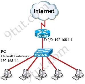
To make above topology work we need to:
+ Configure IP addresses on two interfaces of the Router. Suppose the IP address of Fa0/0 interface (the interface connecting to the switch) is 192.168.1.1.
+ Assign the IP addresses, default gateways and DNS servers on all PCs. In this case we have to set the default gateways to Fa0/0 interface (with the IP address 192.168.1.1) of the router. This can be done manually or automatically via DHCP.
READ MORE…
In the previous VLAN tutorial we learned how to use VLAN to segment the network and create “logical” broadcast domains. In this tutorial we will learn about InterVLAN Routing.
What is InterVLAN routing?
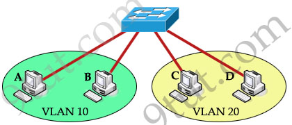
As we learned, devices within a VLAN can communicate with each other without the need of Layer 3 routing. But devices in separate VLANs require a Layer 3 routing device to communicate with one another. For example, in the topology below host A and B can communicate with each other without a router in the same VLAN 10; host C and D can communicate in the same VLAN 20. But host A can’t communicate with host C or D because they are in different VLANs.
To allow hosts in different VLANs communicate with each other, we need a Layer 3 device (like a router) for routing:
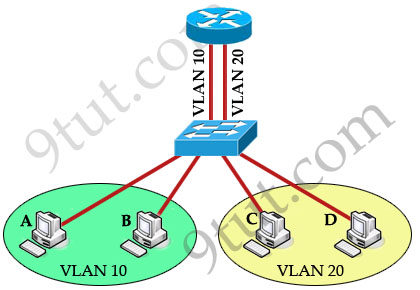
The routing traffic from one VLAN to another VLAN is called InterVLAN routing.
READ MORE…
In the previous tutorial we learned about the boot sequence of a Cisco router/switch. After that, the router will allow us to type commands but in different modes we can only used specific commands. So in this tutorial we will learn about the Command Line Interface (CLI) and different modes in a Cisco router/switch.
Below lists popular modes in Cisco switch/router:
| Router> |
User mode |
| Router# |
Privileged mode |
| Router(config)# |
Configuration mode |
| Router(config-if)# |
Interface level (within configuration mode) |
| Router(config-router)# |
Routing engine level (within configuration mode) |
| Router(config-line)# |
Line level (vty, tty, async) within configuration mode |
Now let’s discuss each mode in more detail
READ MORE…
In this article we will learn about the main components of a Cisco router and how the boot process takes place.
Types of memory
Generally Cisco routers (and switches) contain four types of memory:
Read-Only Memory (ROM): ROM stores the router’s bootstrap startup program, operating system software, and power-on diagnostic test programs (POST).
Flash Memory: Generally referred to simply as “flash”, the IOS images are held here. Flash is erasable and reprogrammable ROM. Flash memory content is retained by the router on reload.
Random-Access Memory (RAM): Stores operational information such as routing tables and the running configuration file. RAM contents are lost when the router is powered down or reloaded. By default, routers look here first for an Internetwork Operating System (IOS) file during boot.
Non-volatile RAM (NVRAM): NVRAM holds the router’s startup configuration file. NVRAM contents are not lost when the router is powered down or reloaded.
READ MORE…
Welcome to the most basic tutorial for networker! Understanding about OSI model is one of the most important tools to help you grasp how networking devices like router, switch, PC… work.
Let’s take an example in our real life to demonstrate the OSI model. Maybe you have ever sent a mail to your friend, right? To do it, you have to follow these steps:
1. Write your letter
2. Insert it into an envelope
3. Write information about sender and receiver on that envelope
4. Stamp it
5. Go to the post office and drop it into a mail inbox
From the example above, I want to imply we have to go through some steps in a specific order to complete a task. It is also applied for two PCs to communicate with each other. They have to use a predefined model, named OSI, to complete each step. There are 7 steps in this model as listed below:
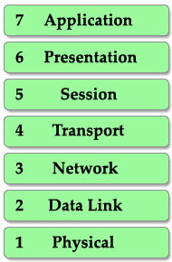
This is also the well-known table of the OSI model so you must take time to learn by heart. A popular way to remember this table is to create a fun sentence with the first letters of each layer. For example: All People Seem To Need Data Processing or a more funny sentence sorted from layer 1 to layer 7: Please Do Not Throw Sausage Pizza Away.
READ MORE…
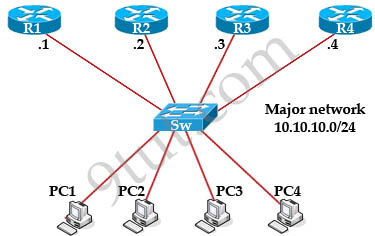
In this article, we will learn how to subnet and make subnetting an easy task.
The table below summarizes the possible network numbers, the total number of each type, and the number of hosts in each Class A, B, and C network.
| |
Default subnet mask |
Range |
| Class A |
255.0.0.0 (/8) |
1.0.0.0 – 126.255.255.255 |
| Class B |
255.255.0.0 (/16) |
128.0.0.0 – 191.255.255.255 |
| Class C |
255.255.255.0 (/24) |
192.0.0.0 – 223.255.255.255 |
Table 1 – Default subnet mask & range of each class
Class A addresses begin with a 0 bit. Therefore, all addresses from 1.0.0.0 to 126.255.255.255 belong to class A (1=0000 0001; 126 = 0111 1110).
The 0.0.0.0 address is reserved for default routing and the 127.0.0.0 address is reserved for loopback testing so they don’t belong to any class.
Class B addresses begin with a 1 bit and a 0 bit. Therefore, all addresses from 128.0.0.0 to 191.255.255.255 belong to class B (128=1000 0000; 191 = 1011 1111).
Class C addresses begin with two 1 bits and a 0 bit. Class C addresses range from 192.0.0.0 to 223.255.255.255 (192 = 1100 0000; 223 = 1101 1111).
Class D & E are used for Multicast and Research purposes and we are not allowed to subnet them so they are not mentioned here.
Note: The number behind the slash notation (/) specifies how many bits are turned on (bit 1). For example:
+ “/8″ equals “1111 1111.0000 0000.0000 0000.0000 0000″ -> 8 bits are turned on (bit 1)
+ “/12″ equals “1111 1111.1111 0000.0000 0000.0000 0000″ -> 12 bits are turned on (bit 1)
+ “/28″ equals “1111 1111.1111 1111.1111 1111.1111 0000″ -> 28 bits are turned on (bit 1)
+ “/32″ equals “1111 1111.1111 1111.1111 1111.1111 1111″ -> 32 bits are turned on (bit 1) and this is also the maximum value because all bits are turned on.
The slash notation (following with a number) is equivalent to a subnet mask. If you know the slash notation you can figure out the subnet mask and vice versa. For example, “/8″ is equivalent to “255.0.0.0″; “/12″ is equivalent to “255.240.0.0″; “/28″ is equivalent to “255.255.255.240″; “/32″ is equivalent to “255.255.255.255″.

The Network & Host parts of each class by default
From the “default subnet mask” shown above, we can identify the network and host part of each class. Notice that in the subnet mask, bit 1 represents for Network part while bit 0 presents for Host part (255 equals to 1111 1111 and 0 equals to 0000 0000 in binary form).
READ MORE…
Let’s start this article with the question: Why do we need Frame Relay?
Let’s take a simple example. Suppose you are working in a big company and your company has just expanded to two new locations. The main site is connected to two branch offices, named Branch 1 & Branch 2 and your boss wants these two branches can communicate with the main site. The most simple solution is to connect them directly (called a leased line) as shown below:

To connect to these two branches, the main site router, HeadQuarter, requires two serial interfaces which a router can provide. But what happens when the company expands to 10 branches, 50 branches? For each point-to-point line, HeadQuarter needs a separate physical serial interface (and maybe a separate CSU/DSU if it is not integrated into the WAN card). As you can imagine, it will need many routers with many interfaces and lots of rack space for the routers and CSU/DSUs. Maybe we should use another solution for this problem? Luckily, Frame Relay can do it!
READ MORE…
In this article we will discuss about Wireless technologies mentioned in CCNA.
Wireless LAN (WLAN) is very popular nowadays. Maybe you have ever used some wireless applications on your laptop or cellphone. Wireless LANs enable users to communicate without the need of cable. Below is an example of a simple WLAN:
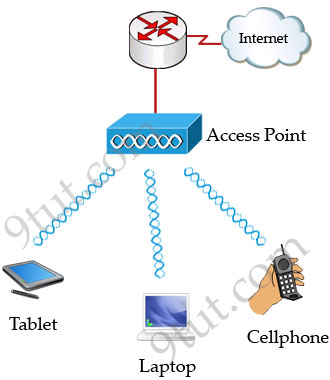
Each WLAN network needs a wireless Access Point (AP) to transmit and receive data from users. Unlike a wired network which operates at full-duplex (send and receive at the same time), a wireless network operates at half-duplex so sometimes an AP is referred as a Wireless Hub.
READ MORE…
VLAN Introduction
“A virtual LAN (VLAN) is a group of networking devices in the same broadcast domain”
It is the concept of VLAN that most of the books are using but it doesn’t help us understand the benefits of VLANs. If you ask “What is a LAN?” you will receive the same answer: it is also a group of networking devices in the same broadcast domain!
To make it clearer, I expanded the above statement into a bit longer statement :)
“A virtual LAN (VLAN) is a group of networking devices in the same broadcast domain, logically”
It means that the devices in the same VLAN may be widely separated in the network, both by geography and location. VLANs logically segment the network into different broadcast domains so that packets are only switched between ports that are designated for the same VLAN.
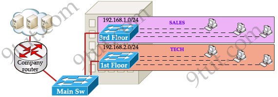
Let’s take an example to understand the benefits of VLAN. Suppose you are working in a big company with many departments, some of them are SALES and TECHNICAL departments. You are tasked to separate these departments so that each of them can only access specific resources in the company.
This task is really easy, you think. To complete this task, you just need to use different networks for these departments and use access-list to allow/deny that network to a specific resource. For example, you assign network 192.168.1.0/24 for SALES and 192.168.2.0/24 for TECH. At the “Company router” you apply an access-list to filter traffic from these networks. Below is the topology of your network without VLANs:
READ MORE…
This topic describes the features that VLAN Trunking Protocol (VTP) offers to support VLANs. To help you understand the basic concept, this is a summary of what VTP is:
“VTP allows a network manager to configure a switch so that it will propagate VLAN configurations to other switches in the network”
VTP minimizes misconfigurations and configuration inconsistencies that can cause problems, such as duplicate VLAN names or incorrect VLAN-type specifications. VTP helps you simplify management of the VLAN database across multiple switches.
VTP is a Cisco-proprietary protocol and is available on most of the Cisco switches.
Why we need VTP?
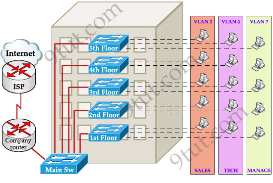
To answer this question, let’s discuss a real and popular network topology.
Suppose you are working in a medium company in a 5-floor office. You assigned each floor to a switch for easy management and of course they can be assigned to different VLANs. For example, your bosses can sit in any floor and still access Manage VLAN (VLAN 7). Your technical colleagues can sit anywhere on the floors to access Technical VLAN (VLAN 4). This is the best design because each person’s permission is not limited by the physical location.
READ MORE…
Internet has been growing extremely fast so the IPv4 addresses are quickly approaching complete depletion. Although many organizations already use Network Address Translators (NATs) to map multiple private address spaces to a single public IP address but they have to face with other problems from NAT (the use of the same private address, security…). Moreover, many other devices than PC & laptop are requiring an IP address to go to the Internet. To solve these problems in long-term, a new version of the IP protocol – version 6 (IPv6) was created and developed.
IPv6 was created by the Internet Engineering Task Force (IETF), a standards body, as a replacement to IPv4 in 1998. So what happened with IPv5? IP Version 5 was defined for experimental reasons and never was deployed.
While IPv4 uses 32 bits to address the IP (provides approximately 232 = 4,294,967,296 unique addresses – but in fact about 3.7 billion addresses are assignable because the IPv4 addressing system separates the addresses into classes and reserves addresses for multicasting, testing, and other specific uses), IPv6 uses up to 128 bits which provides 2128 addresses or approximately 3.4 * 1038 addresses. Well, maybe we should say it is extremely extremely extremely huge :)
READ MORE…
Note: Before reading this article you should understand how STP works. So if you are not sure about STP, please read my article about Spanning Tree Protocol tutorial first.
Rapid Spanning Tree Protocol (RSTP)
One big disadvantage of STP is the low convergence which is very important in switched network. To overcome this problem, in 2001, the IEEE with document 802.1w introduced an evolution of the Spanning Tree Protocol: Rapid Spanning Tree Protocol (RSTP), which significantly reduces the convergence time after a topology change occurs in the network. While STP can take 30 to 50 seconds to transit from a blocking state to a forwarding state, RSTP is typically able to respond less than 10 seconds of a physical link failure.
RSTP works by adding an alternative port and a backup port compared to STP. These ports are allowed to immediately enter the forwarding state rather than passively wait for the network to converge.
RSTP bridge port roles:
* Root port – A forwarding port that is the closest to the root bridge in terms of path cost
* Designated port – A forwarding port for every LAN segment
* Alternate port – A best alternate path to the root bridge. This path is different than using the root port. The alternative port moves to the forwarding state if there is a failure on the designated port for the segment.
* Backup port – A backup/redundant path to a segment where another bridge port already connects. The backup port applies only when a single switch has two links to the same segment (collision domain). To have two links to the same collision domain, the switch must be attached to a hub.
* Disabled port – Not strictly part of STP, a network administrator can manually disable a port
Now let’s see an example of three switches below:

READ MORE…
To provide for fault tolerance, many networks implement redundant paths between devices using multiple switches. However, providing redundant paths between segments causes packets to be passed between the redundant paths endlessly. This condition is known as a bridging loop.
(Note: the terms bridge, switch are used interchangeably when discussing STP)
To prevent bridging loops, the IEEE 802.1d committee defined a standard called the spanning tree algorithm (STA), or spanning tree protocol (STP). Spanning-Tree Protocol is a link management protocol that provides path redundancy while preventing undesirable loops in the network. For an Ethernet network to function properly, only one active path can exist between two stations.
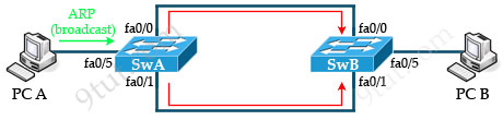
Let’s see a situation when there is no loop-avoidance process in operation. Suppose you have two switches connected with redundant links. One switch connected to PC A and the other switch connected to PC B.
Now PC A wants to talk to PC B. It then sends a broadcast, say an Address Resolution Protocol (ARP) to find out where the location of PC B, the green arrow shows a broadcast frame sent by PC A.
When the switch A receives a broadcast frame, it forwards that frame to all ports except the port where it receives the request -> SwA forwards that ARP frame out of fa0/0 and fa0/1 ports.
READ MORE…
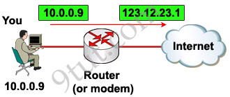
To go to the Internet we need to get an public IP address and it is unique all over the world. If each host in the world required a unique public IP address, we would have run out of IP address years ago. But by using Network Address Translation (NAT) we can save tons of IP addresses for later uses. We can understand NAT like this:
“NAT allows a host that does not have a valid registered IP address to communicate with other hosts through the Internet”
For example your computer is assigned a private IP address of 10.0.0.9 and of course this address can not be routed on the internet but you can still access the internet. This is because your router (or modem) translates this address into a public IP address, 123.12.23.1 for example, before routing your data into the internet.
READ MORE…
In this tutorial we will learn about access list.
Access control lists (ACLs) provide a means to filter packets by allowing a user to permit or deny IP packets from crossing specified interfaces. Just imagine you come to a fair and see the guardian checking tickets. He only allows people with suitable tickets to enter. Well, an access list’s function is same as that guardian.
Access lists filter network traffic by controlling whether packets are forwarded or blocked at the router’s interfaces based on the criteria you specified within the access list.
To use ACLs, the system administrator must first configure ACLs and then apply them to specific interfaces. There are 3 popular types of ACL: Standard, Extended and Named ACLs.
READ MORE…
In this tutorial we will learn about RIP routing protocol
Routing Information Protocol (RIP) is a distance-vector routing protocol. RIP sends the complete routing table out to all active interfaces every 30 seconds. RIP only uses hop count (the number of routers) to determine the best way to a remote network.
Note: RIP v1 is a classful routing protocol but RIP v2 is a classless routing protocol.
Classful routing protocols do not include the subnet mask with the network address in routing updates, which can cause problems with discontiguous subnets or networks that use Variable-Length Subnet Masking (VLSM). Fortunately, RIPv2 is a classless routing protocol so subnet masks are included in the routing updates, making RIPv2 more compatible with modern routing environments.
Distance vector protocols advertise routing information by sending messages, called routing updates, out the interfaces on a router
READ MORE…
In this article we will mention about the EIGRP protocol.
In the past, Enhanced Interior Gateway Routing Protocol (EIGRP) is a Cisco-proprietary routing protocol but from March-2013 Cisco opens up EIGRP as an open standard in order to help companies operate in a multi-vendor environment. EIGRP is a classless routing protocol, meaning that it sends the subnet mask of its interfaces in routing updates, which use a complex metric based on bandwidth and delay.
EIGRP is referred to as a hybrid routing protocol because it has the characteristics of both distance-vector and link-state protocols but now Cisco refers it as an advanced distance vector protocol.
Notice: the term “hybrid” is misleading because EIGRP is not a hybrid between distance vector and link-state routing protocols. It is a distance vector routing protocol with enhanced features.
EIGRP is a powerful routing protocol and it is really standout from its ancestor IGRP. The main features are listed below:
+ Support VLSM and discontiguous networks
+ Use Reliable Transport Protocol (RTP) to delivery and reception of EIGRP packets
+ Use the best path selection Diffusing Update Algorithm (DUAL), guaranteeing loop-free paths and backup paths throughout the routing domain
+ Discover neighboring devices using periodic Hello messages to discover and monitor connection status with its neighbors
+ Exchange the full routing table at startup and send partial* triggered updates thereafter (not full updates like distance-vector protocols) and the triggered updates are only sent to routers that need the information. This behavior is different from the link-state protocol in which an update will be sent to all the link-state routers within that area. For example, EIGRP will send updates when a new link comes up or a link becoming unavailable
+ Supports multiple protocols: EIGRP can exchange routes for IPv4, IPv6, AppleTalk and IPX/SPX networks
+ Load balancing: EIGRP supports unequal metric load balancing, which allows administrators to better distribute traffic flow in their networks.
* Notice: The term “partial” means that the update only includes information about the route changes.
READ MORE…
In this article we will learn about the OSPF Routing Protocol
Open-Shortest-Path-First (OSPF) is the most widely used interior gateway protocol routing protocol on the world because it is a public (non-proprietary) routing protocol while its biggest rival, EIGRP, is a Cisco proprietary protocol so other vendors can’t use it (edit: EIGRP has become a public routing protocol since 2013). OSPF is a complex link-state routing protocol. Link-state routing protocols generate routing updates only when a change occurs in the network topology. When a link changes state, the device that detected the change creates a link-state advertisement (LSA) concerning that link and sends to all neighboring devices using a special multicast address. Each routing device takes a copy of the LSA, updates its link-state database (LSDB), and forwards the LSA to all neighboring devices.
Note:
+ OSPF routers use LSA (Link State Advertisement)to describe its link state. LSDB stores all LSAs.
+ A router uses Router LSA to describe its interface IP addresses.
+ After OSPF is started on a router, it creates LSDB that contains one entry: this router’s Router LSA.
There are five types of OSPF Link-State Packets (LSPs).
READ MORE…


