
InterVLAN Routing Tutorial – Premium Tutorial
In the previous VLAN tutorial we learned how to use VLAN to segment the network and create “logical” broadcast domains. In this tutorial we will learn about InterVLAN Routing.
What is InterVLAN routing?
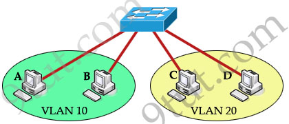
As we learned, devices within a VLAN can communicate with each other without the need of Layer 3 routing. But devices in separate VLANs require a Layer 3 routing device to communicate with one another. For example, in the topology below host A and B can communicate with each other without a router in the same VLAN 10; host C and D can communicate in the same VLAN 20. But host A can’t communicate with host C or D because they are in different VLANs.
To allow hosts in different VLANs communicate with each other, we need a Layer 3 device (like a router) for routing:
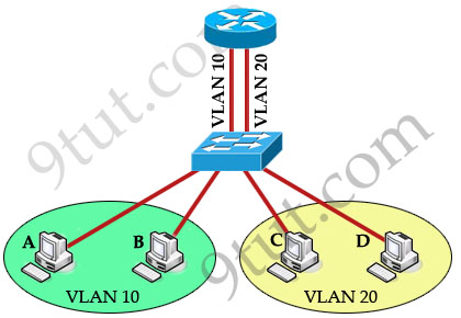
The routing traffic from one VLAN to another VLAN is called InterVLAN routing.


thank you this is really good information. Keep up the good work
its wonderful… congrats!!!
Hi, there are minor wrong word on “Create sub-interfaces, set 802.1Q trunking protocol and ip address on each sub-interface”
Router(config)#interface f0/0
Router(config-if)#no shutdown
(Note: The main interface f0/0 doesn’t need an IP address but it must be turned on)
Router(config-if)#interface f0/0.0 (before create the sub interface, it suppose still in interface mode)
Router(config-subif)#encapsulation dot1q 10
Router(config-subif)#ip address 192.168.1.1 255.255.255.0
Router(config-subif)#interface f0/0.1
Router(config-subif)#encapsulation dot1q 20 (i amend to dot1q, as u wrote to dot11)
Router(config-subif)#ip address 192.168.2.1 255.255.255.0
Correct me if i am wrong, I am new to CCNA. :-)
@Jien: Yes, it is a mistake in my tutorial. Thanks for your detection. I updated it!
Excellent stuff, thanks alot mate.
hi 9tut, i just did the Layer 3 switch configs just as shown on the figure…but still hosts on VLAN 10 cannot communicate with VLAN 20, but both hosts on each VLANs can ping there own gateway. Was there any missing additional commands on the figure? thanks alot…
@AGP: Did you assign the default gateway on the PC?
@9tut: yup i assign the default gateway on the PCs?
By the way, i already figured it out… I haven’t enable this command on the Layer 3 switch…
switch(config)#ip routing
Please include this command in the figure, because other newbies might not figure it out that easily….
By default, Layer 3 switches functions as Layer 2 switches unless its routing capabilities are enabled…
Thanks alot 9tut!
@AGP: That command was added in the “Switch Configuration” (the first line).
sorry i would like to know how can i explain my problem
rtchuembou@yahoo.fr
Please can anyone send me ( danielagboh@yahoo.com ) the latest. SIMS / LABS Questions on CCNA Exams, I am writing next week.Thx
Hello 9tut, I was wondering if your layer-3 switch configuration was incomplete. Don’t you have to configure each of the four ports attached to the switch, as was done in the “router on a stick” configuration?
Switch configuration
ip routing
!
interface FastEthernet0/1 (Should be: interface range fa0/1-2)
switchport access vlan 10
switchport mode access
!
interface FastEthernet0/2 (Should be: interface range fa0/3-4)
switchport access vlan 20
switchport mode access
!
Please let me know if I am missing something.
Thank you for all of your hard work. Your site is very helpful.
@Blake: Yes, the above configuration is only an example of configuring two hosts in different VLANs. In fact you have to do it on 4 interfaces.
good work man..:)
Ya thats what I’m here for Matt. Thank you for your comment too, sorry for the late reply, but I ellary do appreciate you stopping by and leaving a quick note. It helps fuel my motivation to keep going. I hope I was able to help and move you closer to your next Cisco Certification.
SPLENDID!!! Thank you for this wonderful information.
Cheers!!
Hi everyone,
I am currently using cisco catalyst 3750 series (POE-48) switch.
I was given a scenario to test out. But there is some problem.
Requirements: PC1 in VLAN 10 able to ping PC2 in VLAN 30 and vice versa too.
I tried the approach as stated in the layer 3 switch in 9tut, but i still not able get the hosts to ping each other.
My current Switch Configuration file is in the url below.
http://pastebin.ca/2151923
1. Create 4 VLANS
VLAN 10 NAME: Server_VLAN
VLAN 15 NAME: Client_VLAN
VLAN 20 NAME: Demo_VLAN
VLAN 30 NAME: Test_VLAN
2. Port Assignments
VLAN 10 Fa1/0/1 – 12
VLAN 15 Fa1/0/13 – 24
VLAN 20 Fa1/0/25 – 36
VLAN 30 Fa1/0/37 – 43
3. IP
VLAN 10 10.1.10.0/24
VLAN 15 10.1.15.0/24
VLAN 20 10.1.20.0/24
VLAN 30 10.1.30.0/24
It works! realises it my window firewall issues! thanks!
Thank you 9tut!
Hi I’ve read this and I agree but I still can’t get my lab running can anyone point out whaere I’m going wrong please?
Here are the details
Can’t understand why inter VLAN routing is failing on a Layer 3 Cisco 3560
Cisco 3560 can ping all endpoints and google DNS 8.8.8.8
Basic setup
VLAN 10
192.168.17.1 (Host/router)
192.168.17.200 (VLAN Address)
VLAN 20
192.168.20.1 (Host)
192.168.20.200 (VLAN Address)
PC in Vlan 20 can’t ping 192.168.17.1 but can ping 192.168.17.200 and 192.168.20.200 trace route gets as far as 192.168.20.200
This is the config
Switch>
Switch>en
Switch#sh run
Building configuration…
Current configuration : 2122 bytes
!
version 12.2
no service pad
service timestamps debug uptime
service timestamps log uptime
no service password-encryption
!
hostname Switch
!
!
no aaa new-model
system mtu routing 1500
ip subnet-zero
ip routing
!
!
!
!
no file verify auto
spanning-tree mode pvst
spanning-tree extend system-id
!
vlan internal allocation policy ascending
!
!
interface FastEthernet0/1
switchport access vlan 10
switchport mode access
!
interface FastEthernet0/2
switchport access vlan 10
switchport mode access
spanning-tree portfast
!
interface FastEthernet0/3
switchport mode access
!
interface FastEthernet0/4
switchport mode access
!
interface FastEthernet0/5
switchport mode access
!
interface FastEthernet0/6
switchport mode access
!
interface FastEthernet0/7
switchport mode access
!
interface FastEthernet0/8
switchport mode access
!
interface FastEthernet0/9
switchport mode access
!
interface FastEthernet0/10
switchport mode access
!
interface FastEthernet0/11
switchport mode access
!
interface FastEthernet0/12
switchport mode access
!
interface FastEthernet0/13
switchport mode access
!
interface FastEthernet0/14
switchport mode access
!
interface FastEthernet0/15
switchport mode access
!
interface FastEthernet0/16
switchport mode access
!
interface FastEthernet0/17
switchport mode access
!
interface FastEthernet0/18
switchport mode access
!
interface FastEthernet0/19
switchport mode access
!
interface FastEthernet0/20
switchport mode access
!
interface FastEthernet0/21
switchport mode access
!
interface FastEthernet0/22
switchport mode access
!
interface FastEthernet0/23
switchport access vlan 20
switchport mode access
!
interface FastEthernet0/24
switchport access vlan 20
switchport mode access
!
interface GigabitEthernet0/1
!
interface GigabitEthernet0/2
!
interface Vlan1
ip address 10.1.1.1 255.255.255.0
!
interface Vlan10
ip address 192.168.17.200 255.255.255.0
!
interface Vlan20
ip address 192.168.20.200 255.255.255.0
!
ip classless
ip route 0.0.0.0 0.0.0.0 192.168.17.1
ip http server
!
!
!
control-plane
!
!
line con 0
line vty 0 4
login
line vty 5 15
login
!
end
Switch#sh vlan
VLAN Name Status Ports
—- ——————————– ——— ——————————-
1 default active Fa0/2, Fa0/3, Fa0/4, Fa0/5
Fa0/6, Fa0/7, Fa0/8, Fa0/9
Fa0/10, Fa0/11, Fa0/12, Fa0/13
Fa0/14, Fa0/15, Fa0/16, Fa0/17
Fa0/18, Fa0/19, Fa0/20, Fa0/21
Fa0/22, Gi0/1, Gi0/2
10 vlan10 active Fa0/1
20 vlan20 active Fa0/23, Fa0/24
1002 fddi-default act/unsup
1003 token-ring-default act/unsup
1004 fddinet-default act/unsup
1005 trnet-default act/unsup
VLAN Type SAID MTU Parent RingNo BridgeNo Stp BrdgMode Trans1 Trans2
—- —– ———- —– —— —— ——– —- ——– —— ——
1 enet 100001 1500 – – – – – 0 0
10 enet 100010 1500 – – – – – 0 0
20 enet 100020 1500 – – – – – 0 0
1002 fddi 101002 1500 – – – – – 0 0
1003 tr 101003 1500 – – – – – 0 0
VLAN Type SAID MTU Parent RingNo BridgeNo Stp BrdgMode Trans1 Trans2
—- —– ———- —– —— —— ——– —- ——– —— ——
1004 fdnet 101004 1500 – – – ieee – 0 0
1005 trnet 101005 1500 – – – ibm – 0 0
Remote SPAN VLANs
——————————————————————————
Primary Secondary Type Ports
——- ——— —————– ——————————————
Switch#sh ip int br
Switch#sh ip int brief
Interface IP-Address OK? Method Status Protocol
Vlan1 10.1.1.1 YES NVRAM up down
Vlan10 192.168.17.200 YES NVRAM up up
Vlan20 192.168.20.200 YES NVRAM up up
FastEthernet0/1 unassigned YES unset up up
FastEthernet0/2 unassigned YES unset down down
FastEthernet0/3 unassigned YES unset down down
FastEthernet0/4 unassigned YES unset down down
FastEthernet0/5 unassigned YES unset down down
FastEthernet0/6 unassigned YES unset down down
FastEthernet0/7 unassigned YES unset down down
FastEthernet0/8 unassigned YES unset down down
FastEthernet0/9 unassigned YES unset down down
FastEthernet0/10 unassigned YES unset down down
FastEthernet0/11 unassigned YES unset down down
FastEthernet0/12 unassigned YES unset down down
FastEthernet0/13 unassigned YES unset down down
FastEthernet0/14 unassigned YES unset down down
FastEthernet0/15 unassigned YES unset down down
FastEthernet0/16 unassigned YES unset down down
FastEthernet0/17 unassigned YES unset down down
FastEthernet0/18 unassigned YES unset down down
FastEthernet0/19 unassigned YES unset down down
FastEthernet0/20 unassigned YES unset down down
FastEthernet0/21 unassigned YES unset down down
FastEthernet0/22 unassigned YES unset down down
FastEthernet0/23 unassigned YES unset up up
FastEthernet0/24 unassigned YES unset up up
GigabitEthernet0/1 unassigned YES unset down down
GigabitEthernet0/2 unassigned YES unset down down
00:18:44: %SYS-5-CONFIG_I: Configured from console by consoleh ip route
Codes: C – connected, S – static, R – RIP, M – mobile, B – BGP
D – EIGRP, EX – EIGRP external, O – OSPF, IA – OSPF inter area
N1 – OSPF NSSA external type 1, N2 – OSPF NSSA external type 2
E1 – OSPF external type 1, E2 – OSPF external type 2
i – IS-IS, su – IS-IS summary, L1 – IS-IS level-1, L2 – IS-IS level-2
ia – IS-IS inter area, * – candidate default, U – per-user static route
o – ODR, P – periodic downloaded static route
Gateway of last resort is 192.168.17.1 to network 0.0.0.0
C 192.168.20.0/24 is directly connected, Vlan20
C 192.168.17.0/24 is directly connected, Vlan10
S* 0.0.0.0/0 [1/0] via 192.168.17.1
Switch#
i have a topology with one router ,two different vlans and three switches and am to assign dhcp for this vlans
@straut:
I am new to the CCNA, i think you need to set password over the console and telnet.
there you didnt set anything over there
let me know whether it is applicable or not?
Regards
ravi mishra
@blake
You have to set the default gateway as that of vlan address, if not the packet will be dropped
@stuart
I think you have to set the ip address of the Vlan as your default gateway on the pc, so that they will know where the packet has to go.
Sir I made this scenario in packet tracer with your suggested configuration. but I made 3 vlans in the palace of these 2s. (VLAN2, VLAN3, VLAN10).
But all vlans are unable to communicate with each other.
I paste down my configuration :-
SWITCH
#do sh run
Building configuration…
Current configuration : 1073 bytes
!
version 12.1
no service timestamps log datetime msec
no service timestamps debug datetime msec
no service password-encryption
!
hostname Switch
!
!
spanning-tree mode pvst
!
interface FastEthernet0/1
switchport mode trunk
!
interface FastEthernet0/2
switchport access vlan 2
!
interface FastEthernet0/3
switchport access vlan 3
!
interface FastEthernet0/4
switchport access vlan 10
!
interface FastEthernet0/5
!
interface FastEthernet0/6
!
interface FastEthernet0/7
!
interface FastEthernet0/8
!
interface FastEthernet0/9
!
interface FastEthernet0/10
!
interface FastEthernet0/11
!
interface FastEthernet0/12
!
interface FastEthernet0/13
!
interface FastEthernet0/14
!
interface FastEthernet0/15
!
interface FastEthernet0/16
!
interface FastEthernet0/17
!
interface FastEthernet0/18
!
interface FastEthernet0/19
!
interface FastEthernet0/20
!
interface FastEthernet0/21
!
interface FastEthernet0/22
!
interface FastEthernet0/23
!
interface FastEthernet0/24
!
interface Vlan1
no ip address
shutdown
!
!
line con 0
!
line vty 0 4
login
line vty 5 15
login
!
!
end
#do sh vlan
VLAN Name Status Ports
—- ——————————– ——— ——————————-
1 default active Fa0/5, Fa0/6, Fa0/7, Fa0/8
Fa0/9, Fa0/10, Fa0/11, Fa0/12
Fa0/13, Fa0/14, Fa0/15, Fa0/16
Fa0/17, Fa0/18, Fa0/19, Fa0/20
Fa0/21, Fa0/22, Fa0/23, Fa0/24
2 A active Fa0/2
3 D active Fa0/3
10 S active Fa0/4
1002 fddi-default act/unsup
1003 token-ring-default act/unsup
1004 fddinet-default act/unsup
1005 trnet-default act/unsup
VLAN Type SAID MTU Parent RingNo BridgeNo Stp BrdgMode Trans1 Trans2
—- —– ———- —– —— —— ——– —- ——– —— ——
1 enet 100001 1500 – – – – – 0 0
2 enet 100002 1500 – – – – – 0 0
3 enet 100003 1500 – – – – – 0 0
10 enet 100010 1500 – – – – – 0 0
1002 fddi 101002 1500 – – – – – 0 0
1003 tr 101003 1500 – – – – – 0 0
1004 fdnet 101004 1500 – – – ieee – 0 0
1005 trnet 101005 1500 – – – ibm – 0 0
Remote SPAN VLANs
——————————————————————————
Primary Secondary Type Ports
——- ——— —————– ——————————————
ROUTER
#do sh run
Building configuration…
Current configuration : 760 bytes
!
version 12.4
no service timestamps log datetime msec
no service timestamps debug datetime msec
no service password-encryption
!
hostname Router
!
!
!
!
!
!
!
!
!
!
!
!
!
!
spanning-tree mode pvst
!
!
!
!
interface FastEthernet0/0
ip address 200.1.1.2 255.255.255.0
duplex auto
speed auto
shutdown
!
interface FastEthernet0/1
no ip address
duplex auto
speed auto
!
interface FastEthernet0/1.1
encapsulation dot1Q 2
ip address 192.168.1.1 255.255.255.0
!
interface FastEthernet0/1.2
encapsulation dot1Q 3
ip address 192.168.2.1 255.255.255.0
!
interface FastEthernet0/1.3
encapsulation dot1Q 10
ip address 192.168.10.1 255.255.255.0
!
interface Vlan1
no ip address
shutdown
!
ip classless
!
!
!
!
!
!
!
line con 0
line vty 0 4
login
!
!
!
end
@Anu Tiger
interface FastEthernet0/0
ip address 200.1.1.2 255.255.255.0
duplex auto
speed auto
shutdown
can you give an ip from 192.168.4.5 or so and no shutdown
after which in the sh run Vlan 2,3,10 are not displayed hence you have to go inside and do
no shutdown on all the vlan interface.
after which, what is the default gateway address you assign to the pc. What you can do is assign a ip address to each vlan according to what you have given to the router sub interface and from the global configuration mode you can give a ip default gateway xxxx.xxxx.xxxx.xxxx. (that of the router)initial interface say s0/0 and not the sub interface
or you can give the default gateway on each pc to that you have configured on the sub interface
Hope this works please post if you still encounter any problem.
Best Regards,
XXXXXXXXX
Why is the ACL applied to F0/1 out and not F0/0 in. Shouldn’t extended ACLs be applied nearest to the source, F0/0 in?
Whoa sorry… Wrong tab
Excellent work! I like your website. My question is- if I do everything from this site and dont do any dumps. Will I pass? I find this website very useful and personally feel I dont need to study from any dumps. Pls suggest.
thank u i am understand
what is command…to convert L3 switch as router……..
I need InterVLAN Routing tutorial from 9tut.com
Can anyone send me at haigoo77@live.com
thanks for help
Great job guys!!, excellent study material and explanations.
Hi guys,9tut.com is so good!
Could anybody has the whole can send me?
andy78714@gmail.com
Thanks a lot!!
Hi Stuart,
would u checked the ip configuration of the PC under vlan 20 ?
does it have the default gateway of 192.168.20.200 .
In order to communicate between intervlan the packet first has to reach the default gateway which is nothing but the virtual interface Vlan20.
Regards,
Suresh
@fersue: Do you see the 25 New Updated Questions on this site? It is a part of the Premium Membership.
ii have cleared the exam .the dumps available in this site http://ruturl.com/tja
Great Tutorial. Thank you! it’s worth every penny to pay for Premium Membership.
Yes Stuart,
Mini is correct!
Please do configure a default gateway for each vlan domain
Can you please provide the configuration example of both ends. Would be great help. Thanks!!!
Can anyone send inter vlan routing configuration detail steps.
small mistake contain
@ stuart: I think Its easier to use router on a stick. And I don’t see any interfaces configured as trunk links.Like the interfaces connecting your router to the switch. Try that if it’ll work: )
Inter Vlan routing is easy. You need to set up DHCP aswell and make sure the default gateway is pointed correctly for each vlan.
Conf Term
Service Dhcp
ip dhcp pool (name)
network (Network) (Subnet)
Default router (IP of Gateway)
DNS Server 8.8.8.8
It should all work for you guys. IVR will work if no DHCP just have to manually set your gateway/IP/Subnet etc.