
OSI Model Tutorial
Welcome to the most basic tutorial for networker! Understanding about OSI model is one of the most important tools to help you grasp how networking devices like router, switch, PC… work.
Let’s take an example in our real life to demonstrate the OSI model. Maybe you have ever sent a mail to your friend, right? To do it, you have to follow these steps:
1. Write your letter
2. Insert it into an envelope
3. Write information about sender and receiver on that envelope
4. Stamp it
5. Go to the post office and drop it into a mail inbox
From the example above, I want to imply we have to go through some steps in a specific order to complete a task. It is also applied for two PCs to communicate with each other. They have to use a predefined model, named OSI, to complete each step. There are 7 steps in this model as listed below:
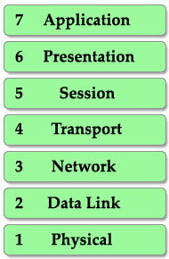
This is also the well-known table of the OSI model so you must take time to learn by heart. A popular way to remember this table is to create a fun sentence with the first letters of each layer. For example: All People Seem To Need Data Processing or a more funny sentence sorted from layer 1 to layer 7: Please Do Not Throw Sausage Pizza Away.
There are two notices about this table:
1. First, the table is arranged from top to bottom (numbering from 7 to 1). Each step is called a “layer” so we have 7 layers (maybe we usually call them “layers” to make them more… technical ^^).
When a device wants to send information to another one, its data must go from top to bottom layer. But when a device receives this information, it must go from bottom to top to “decapsulate” it. In fact, the reverse action at the other end is very natural in our life. It is very similar when two people communicate via mail. First, the writer must write the letter, insert it into an envelope while the receiver must first open the envelope and then read the mail. The picture below shows the whole process of sending and receiving information.
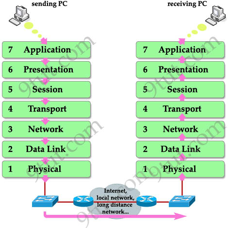
Note: The OSI model layers are often referred to by number than by name (for example, we refer saying “layer 3″ to “network layer”) so you should learn the number of each layer as well.
2. When the information goes down through layers (from top to bottom), a header is added to it. This is called encapsulation because it is like wrapping an object in a capsule. Each header can be understood only by the corresponding layer at the receiving side. Other layers only see that layer’s header as a part of data.
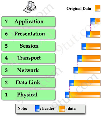
At the receiving side, corresponding header is stripped off in the same layer it was attached.
Understand each layer
Layer 7 – Application layer
This is the closest layer to the end user. It provides the interface between the applications we use and the underlying layers. But notice that the programs you are using (like a web browser – IE, Firefox or Opera…) do not belong to Application layer. Telnet, FTP, email client (SMTP), HyperText Transfer Protocol (HTTP) are examples of Application layer.
Layer 6 – Presentation layer
This layer ensures the presentation of data, that the communications passing through are in the appropriate form for the recipient. In general, it acts as a translator of the network. For example, you want to send an email and the Presentation will format your data into email format. Or you want to send photos to your friend, the Presentation layer will format your data into GIF, JPG or PNG… format.
Layer 5 – Session layer
Layer 5 establishes, maintains and ends communication with the receiving device.
Layer 4 – Transport layer
This layer maintains flow control of data and provides for error checking and recovery of data between the devices. The most common example of Transport layer is Transmission Control Protocol (TCP) and User Datagram Protocol (UDP).
Layer 3 – Network layer
This layer provides logical addresses which routers will use to determine the path to the destination. In most cases, the logic addresses here means the IP addresses (including source & destination IP addresses).
Layer 2 – Data Link Layer
The Data Link layer formats the message into a data frame, and adds a header containing the hardware destination and source address to it. This header is responsible for finding the next destination device on a local network.
Notice that layer 3 is responsible for finding the path to the last destination (network) but it doesn’t care about who will be the next receiver. It is the Layer 2 that helps data to reach the next destination.
This layer is subdivide into 2 sub-layers: logical link control (LLC) and media access control (MAC).
The LLC functions include:
+ Managing frames to upper and lower layers
+ Error Control
+ Flow control
The MAC sublayer carries the physical address of each device on the network. This address is more commonly called a device’s MAC address. MAC address is a 48 bits address which is burned into the NIC card on the device by its manufacturer.
Layer 1 – Physical layer
The Physical Layer defines the physical characteristics of the network such as connections, voltage levels and timing.
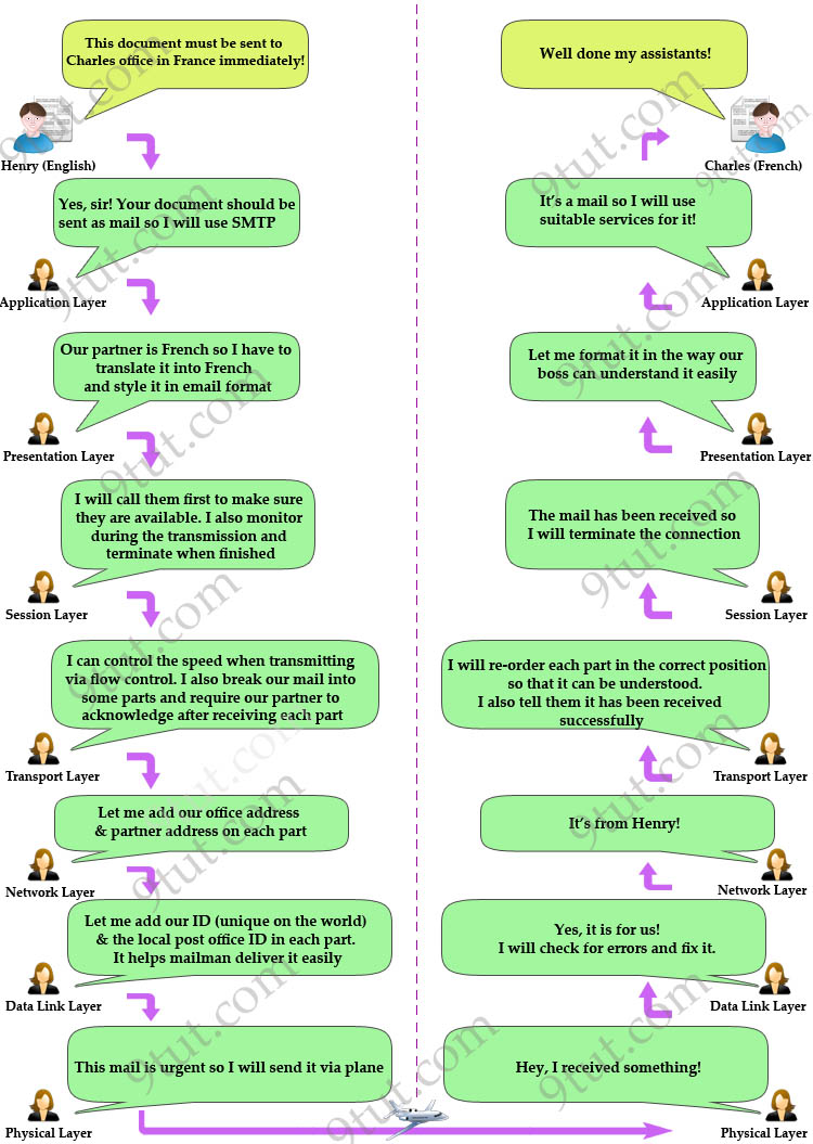
To help you remember the functions of each layer more easily, I created a fun story in which Henry (English) wants to send a document to Charles (French) to demonstrate how the OSI model works.
Lastly, I summarize all the important functions of each layer in the table below (please remember them, they are very important knowledge you need to know about OSI model):
| Layer | Description | Popular Protocols | Protocol Data Unit | Devices operate in this layer |
| Application | + User interface | HTTP, FTP, TFTP, Telnet, SNMP, DNS… | Data | |
| Presentation | + Data representation, encryption & decryption |
+ Video (WMV, AVI…) |
Data | |
| Session | + Set up, monitor & terminate the connection session | + SQL, RPC, NETBIOS names… | Data | |
| Transport | + Flow control (Buffering, Windowing, Congestion Avoidance) helps prevent the loss of segments on the network and the need for retransmission | + TCP (Connection-Oriented, reliable) + UDP (Connectionless, unreliable) |
Segment | |
| Network | + Path determination + Source & Destination logical addresses |
+ IP + IPX + AppleTalk |
Packet/Datagram | Router |
| Data Link |
+ Physical addresses Includes 2 layers: |
+ LAN + WAN (HDLC, PPP, Frame Relay…) |
Frame | Switch, Bridge |
| Physical |
Encodes and transmits data bits + Electric signals |
+ FDDI, Ethernet | Bit (0, 1) | Hub, Repeater… |
Note: In fact, OSI is just is a theoretical model of networking. The practical model used in modern networks is the TCP/IP model. You may think “Hm, it’s just theoretic and has no use in real life! I don’t care!” but believe me, you will use this model more often than the TCP/IP model so take time to grasp it, you will not regret – I promise :)


Ethernet is also a data link layer protocol,isn’t it?
@udana
ethernet operates at both L1 and L2
http://en.wikipedia.org/wiki/Ethernet
ONe WORD TO DESCRIBE
////
AWESOME
BUT CAN ANY ONE TELL WATS THE DIFFERENCE B/w OSI AND TCI/IP ?
@shahbuddin
OSI is just a concept used to better explain what goes on when data goes from point A to point B
TCP/IP is a concept that also applies in the real world
Awesome job!!! 9tut
can anyone tell me how a host to host connection happens?in detail with a diagram ?How the ARP request format is created?before that where the packet is stored?all these things?
its a very common question in any interviews.
really useful.
Thanks 9tut
it relay helpless for me
5th of April i will give my exam
this document rally solve my confusions about osi model
well done 9tut..great job
very good explanation
This is one of the best explanation Of OSI i came across
very use full.it’s very easy to study.
hey i liked the explanation for the OSI model,its really simple to remember and explain others.
Its too good to understand … very simplest way with simple examples
Very nice, usefull. excellent :)
I stand and bow my head for such a great explanation.
Thank you and God bless….
great job . .. i like it very very much such a good site for CCNA, thanks [9tut]
Thank u and great job
thanks 9tut for amazing job maked easy to understand
i just want to ask if we r surfing the internet , then are we on receving end or transmitting end
because when we access something by clicking one of the given link , then how OSI layer works, is it works top to bottom or bottom to top , i m little bit confuse, so reply me on ravi.kant651@gmail.com
@ravi
you are a client, you receive
the server is providing you with services, it is transmitting
when we connects through internet , according to OSI layer ,when we access something ,it directly connect to application layer , , so from where the working starts, according to you ,we r on recieving end , receiving end starts from physical layer
and one thing also, what will be the procedure if i am very first time connect through the internet and using a particular site suppose facebook , then how OSI layers comes into play,
top to bottom or bottom to top
@ravikant: At your side : from top to bottom (sending). When facebook server receives your data it will read from bottom to top (receiving).
Hi, I have a question that is bugging me, it may sound simple: which OSI layer is responsible with dividing information in bits? I suppose it is the Data Link, because I read that it groups the bits in frames, so it may seem logical to me that it also divides the frames into bits before sending them to the Physical Layer. Please let me know if I am wrong or right. Thank you :)
@alexandra: The Physical layer divides the frames into bits before sending out to another device.
thanks for 9tut !!!!!!!!!!!!!!!!!
Hello,
could you be kind to give any word more about flow control (buffering, windowing, congestion avoidence)?
Thanks!
It is very useful for the beginers
جيد هذا أوضح البيان في أوسي
Very Nice and Thanks Too.
To the point, flawless and almost second to none!
Thanks a million.
Please put them into PDF format so we can download.”
Thank u
Thanks a lot. nice writeup
Nothing could be easier than this. Thanks a lot.
Great Job by making it simple
Great explanation, very glad I found this. I have had so much trouble understanding the OSI model until I saw this. Thank you so much for putting the time into making this.
Remember the mnemonic: All People Seem To Need Data Processing or Please Do Not Throw Sausage Pizza Away…!
This is truly awesome… all these i have learned OSI model but today it is in my vein …. gr8 job!!
The way you explained the OSI Model is superb..so Thanks a lot………..
Thank a lot. Very useful explanation.
I have been struggling to build strong foundation of OSI Layers, This was exactly what i was expecting, Hats off to the author!
thx alot for the easy explanation :)
This is awesome, Thanks
Excellent site easy to learn and understand
Good……Thanks
good tutor!
I am from Bangladesh. I am going to sit for the CCNA exam next week. I just want to be premium member of your site to review the questions as my last preparation. I have no bank account moreover no one is known to me who have a credit/visa/master card. Please instruct me how to be a premium member of your site. Thank you:)
can anybody tell me eigrp and rip and bgp works on which layer ?
@kushal
rip and bgp are sometimes considered L4 AND L7 protocols
UDP & RIP = UDP port 520 AND TCP 179 (L4 or L7?)
OSPF = IP protocol 89 (L3)
EIGRP = IP protocol 88 (L3)
IS-IS = CLNS protocol (L2)
i hope this helps.
jide_tade@yahoo.com