
Rapid Spanning Tree Protocol RSTP Tutorial
Note: Before reading this article you should understand how STP works. So if you are not sure about STP, please read my article about Spanning Tree Protocol tutorial first.
Rapid Spanning Tree Protocol (RSTP)
One big disadvantage of STP is the low convergence which is very important in switched network. To overcome this problem, in 2001, the IEEE with document 802.1w introduced an evolution of the Spanning Tree Protocol: Rapid Spanning Tree Protocol (RSTP), which significantly reduces the convergence time after a topology change occurs in the network. While STP can take 30 to 50 seconds to transit from a blocking state to a forwarding state, RSTP is typically able to respond less than 10 seconds of a physical link failure.
RSTP works by adding an alternative port and a backup port compared to STP. These ports are allowed to immediately enter the forwarding state rather than passively wait for the network to converge.
RSTP bridge port roles:
* Root port – A forwarding port that is the closest to the root bridge in terms of path cost
* Designated port – A forwarding port for every LAN segment
* Alternate port – A best alternate path to the root bridge. This path is different than using the root port. The alternative port moves to the forwarding state if there is a failure on the designated port for the segment.
* Backup port – A backup/redundant path to a segment where another bridge port already connects. The backup port applies only when a single switch has two links to the same segment (collision domain). To have two links to the same collision domain, the switch must be attached to a hub.
* Disabled port – Not strictly part of STP, a network administrator can manually disable a port
Now let’s see an example of three switches below:

Suppose all the switches have the same bridge priority so the switch with lowest MAC address will become root bridge -> Sw1 is the root bridge and therefore all of its ports will be Designated ports (forwarding).
Two ports fa0/0 on Sw2 & Sw3 are closest to the root bridge (in terms of path cost) so they will become root ports.
On the segment between Sw2 and Sw3, because Sw2 has lower MAC than Sw3 so it will advertise better BPDU on this segment -> fa0/1 of Sw2 will be Designated port and fa0/1 of Sw3 will be Alternative port.
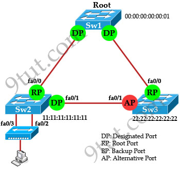
Now for the two ports connecting to the hub, we know that there will have only one Designated port for each segment (notice that the two ports fa0/2 & fa0/3 of Sw2 are on the same segment as they are connected to a hub). The other port will be Backup port according to the definition of Backup port above. But how does Sw2 select its Designated and Backup port? The decision process involves the following parameters inside the BPDU:
* Lowest path cost to the Root
* Lowest Sender Bridge ID (BID)
* Lowest Port ID
Well, both fa0/2 & fa0/3 of Sw2 has the same “path cost to the root” and “sender bridge ID” so the third parameter “lowest port ID” will be used. Because fa0/2 is inferior to fa0/3, Sw2 will select fa0/2 as its Designated port.
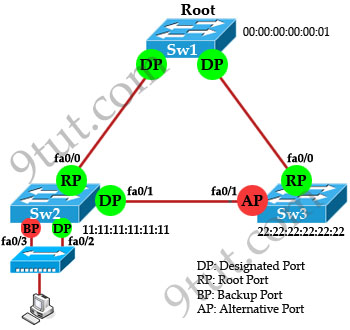
Note: Alternative Port and Backup Port are in discarding state.
RSTP Port States:
There are only three port states left in RSTP that correspond to the three possible operational states. The 802.1D disabled, blocking, and listening states are merged into the 802.1w discarding state.
* Discarding – the port does not forward frames, process received frames, or learn MAC addresses – but it does listen for BPDUs (like the STP blocking state)
* Learning – receives and transmits BPDUs and learns MAC addresses but does not yet forward frames (same as STP).
* Forwarding – receives and sends data, normal operation, learns MAC address, receives and transmits BPDUs (same as STP).
| STP State (802.1d) | RSTP State (802.1w) |
| Blocking | Discarding |
| Listening | Discarding |
| Learning | Learning |
| Forwarding | Forwarding |
| Disabled | Discarding |
Although the learning state is also used in RSTP but it only takes place for a short time as compared to STP. RSTP converges with all ports either in forwarding state or discarding state.
RSTP Quick Summary:
RSTP provides faster convergence than 802.1D STP when topology changes occur.
* RSTP defines three port states: discarding, learning, and forwarding.
* RSTP defines five port roles: root, designated, alternate, backup, and disabled.
Note: RSTP is backward compatible with legacy STP 802.1D. If a RSTP enabled port receives a (legacy) 802.1d BPDU, it will automatically configure itself to behave like a legacy port. It sends and receives 802.1d BPDUs only.


Great explanation!!!
thanx alot i was really confusing by this topic
thanks good
its too confusing topic in hole ccna study
Hi,
Good presentation. I had confusion in Backup port and its essence in RSTP, now i am clear with it. Can you explain the Two way hand shake process that takes place in Point to point Ports when there is any link failure. I am asking this for the completeness of RSTP. If possible please include it in this tutorial.
Great work.
Thanks again.
Regards,
Vinay G
@9tut
referring to RSTP port states:
it defines discarding, learning and forwarding states. (blocking and listening states in legacy STP are eliminated by discarding state in RSTP)
Great Tutorial! Thx!
simplified……. Thanks
nice work u did wid RSTp tanx.
Thank you 9tut
Thanks 9tut once again, you have made our listening, learning and forwarding states easier… :-)
nic explanation
@9tut,
What is the reconvergence time of rstp after link failure?
Thanks in advance
@Moloy: There is not a fixed time for RSTP convergence but typically it is less than 10 seconds.
@9tut,
Thanks. But how it will be less than 10 seconds because it will take 6 seconds for max-age time and 15 seconds for learning to forwarding mode. So, it will take at least 21 seconds. I am getting confused, please make me clear.
@Moloy
That’s beyond the CCNA level.
visit this link:
http://www.cisco.com/en/US/docs/switches/lan/catalyst2950/software/release/12.1_9_ea1/configuration/guide/swmstp.html#wp1039828
“Alternate port – A best alternate path to the root bridge. This path is different than using the root port. The alternative port moves to the forwarding state if there is a failure on the designated port for the segment.”
The alternate port will become forwarding if there is a failure in the root port (not designated port)
nice presentation
Great article ! Thank you
In the “quick summary” second statement, is it a typo ? “discarding, listening and forwarding”, should “listening” be “Learning” ?
@nc: Yes, thank for your detection. I updated it!
Excellent explanation.
Tahnk you for making learning so easy,i really appreciate
great tutorial….
good man…
@9TUT
YOU ROCK!!!!!!!!!!!!This is the best tutorial that i have come across. it covers all that you need to know in a simplified and understandable manner. THANKS!
now i understand….thanks a lot 9tut
You are great, 9tut administrator.
Simple & easy.
Thanx
Thank you very much 9tut great explanation…..
great presentation…i was really confused with this alt and backup port concept..thanks a lot..
nice and clear explanation :-)
crystal clear. You should write a cisco book!
Excellent explanation. Thanks a lot.
good tutorial.easy to understand.now i understand about RSTP.thanks 9tut..
Guys, I have a question about RPVST.
When we elect Alternative port on switches what should we do?
1) The port of switch become AP if this switch has a bigger past cost to root switch versus the switch which has lower pat cost to root bridge? Is it right?
2) If the costs to root bridge are same we should compare MAC of the switches. If one of two switches has lower MAC than second switch, its port become DP and port of second switch become AP? Is it right?
Thanks
awesome presentation
Thank you…… it is very easy to understand
….appriciateble the way of explain and scenario
should have explained a link failure case .,.,or a new link added case
I had to read this (RSTP) a few times to understand it. Thanks 9tut for this site, is very helpful.
Thank you.Well Explained
Great explanation :)
I have one question here.. There is a concept of edge port in RSTP.. Edge ports are those which are connected to end stations. These ports do not recieve any incoming BPDU’s on them and hence do not participate in STP algorithm.
When we connect Switch Sw2 in the above example to a hub wouldnt RSTP put both the ports in Edge mode as the hub would not send any BPDU’s to these ports?
Sorry forgot to mention that my question is when one port is connected from Switch to hub.. Not 2 as in the example..
Wow thank a lot grate explaining ……
Hi,
I am having a doubt in the RSTP convergence time. How the convergence time is less than 1 seconds. If the link down happens the switch should wait for minimum 3 hello packets so it will take 6 seconds to identify the link down then how come the convergence time is 1 sec?
Can some one help me to understand this?
@Karthik….where did u read the 1 sec convergence time?
9tut says this about RSTP convergence time
“Rapid Spanning Tree Protocol (RSTP), which significantly reduces the convergence time after a topology change occurs in the network. While STP can take 30 to 50 seconds to transit from a blocking state to a forwarding state, RSTP is typically able to respond less than 10 seconds of a physical link failure.”
pls can anybody send me a vce regestration key ,am prepering for my ccna exam next month and i could’nt get through all questions in the file i dowloaded at examcollection bcos of registration key.thanks alot email. rothitler@yahoo.com .
@ropam and karthik , yes RSTP is able to respond to a physical link failure in less than 10 seconds because of the hello timers of BPDU’s , in case a neighbor misses three consecutive BPDU’s from its directly connected neighbor , it assumes the neighbor to be dead. each BPDU is sent out every 2 seconds every switch port, 3 BPDU’s means a total of 6 seconds.
nice explained…thank you
When we say “Suppose all the switches have the same bridge priority so the switch with lowest MAC address will become root bridge “…
As a switch has many interfaces, it has many MAC addresses too.. Which one would we choose ?
@Koopotang: Each switch only has 1 MAC address even they have many interfaces. Maybe you are confused about the interfaces on the switch and router: Each interface on a router does have a separate MAC address.