
Frame Relay Tutorial
Let’s start this article with the question: Why do we need Frame Relay?
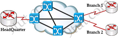
Let’s take a simple example. Suppose you are working in a big company and your company has just expanded to two new locations. The main site is connected to two branch offices, named Branch 1 & Branch 2 and your boss wants these two branches can communicate with the main site. The most simple solution is to connect them directly (called a leased line) as shown below:

To connect to these two branches, the main site router, HeadQuarter, requires two serial interfaces which a router can provide. But what happens when the company expands to 10 branches, 50 branches? For each point-to-point line, HeadQuarter needs a separate physical serial interface (and maybe a separate CSU/DSU if it is not integrated into the WAN card). As you can imagine, it will need many routers with many interfaces and lots of rack space for the routers and CSU/DSUs. Maybe we should use another solution for this problem? Luckily, Frame Relay can do it!
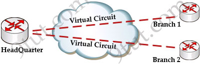
By using Frame Relay we only need one serial interface at the HeadQuarter to connect to all branches. This is also true when we expand to 10 or 50 branches. Moreover, the cost is much lesser than using leased-lines.
Frame Relay is a high-performance WAN protocol that operates at the physical and data link layers of the OSI reference model. It offers lower-cost data transfer when compared to typical point-to-point applications, by using virtual connections within the frame relay network and by combining those connections into a single physical connection at each location. Frame relay providers use a frame relay switch to route the data on each virtual circuit to the appropriate destination.
Maybe these terminologies of Frame Relay are difficult to understand so we will explain them in more detail in this article.
DCE & DTE
The first concept in Frame Relay you must grasp is about DTE & DCE:
+ Data terminal equipment (DTE), which is actually the user device and the logical Frame-relay end-system
+ Data communication equipment (DCE, also called data circuit-terminating equipment), which consists of modem and packet switch
In general, the routers are considered DTE, and the Frame Relay switches are DCE. The purpose of DCE equipment is to provide clocking and switching services in a network. In our example, HeadQuarter, Branch 1 & Branch 2 are DTEs while Frame Relay switches are DCEs.
Virtual Circuits
The logical connection through the Frame Relay network between two DTEs is called a virtual circuit (VC). The term “virtual” here means that the two DTEs are not connected directly but through a network. For example, the HeadQuarter & Branch 1 (or Branch 2) can communicate with each other as if they were directly connected but in fact they are connected through a Frame Relay network with many Frame Relay switches between them.
There are two types of VCs
+ switched virtual circuits (SVCs): are temporary connections that are only used when there is sporadic data transfer between DTE devices across the Frame Relay network. SVC is set up dynamically when needed. SVC connections require call setup and termination for each connection.
+ permanent virtual circuits (PVCs): A predefined VC. A PVC can be equated to a leased line in concept.
Nowadays most service providers offer PVC service only to save additional costs for signaling and billing procedures.


This tutuorial was very helpful!
he website was how do i say it… relevant, finally something that helped me. Many thanks
Very nice, i suggest webmaster can set up a forum, so that we can talk and communicate.
@margaret
http://www.certprepare.com/forum/
HeadQuarter(config-if)#frame-relay map ip 1.1.1.1 23 broadcast
HeadQuarter(config-if)#frame-relay map ip 1.1.1.1 51 broadcast
isnt the second command’s ip address suppose to be
HeadQuarter(config-if)#frame-relay map ip 2.2.2.2 51 broadcast
since its mapping a different subnet of Branch2
@malone: Yes, thanks for your detection. I updated it!
very nice Article :) thanks a lot
Given that this is a tutorial, shouldn’t you use “correct” ip addressing for the frame relay interface? For multipoint, the interfaces should be on the same subnet. If HQ is 9.9.9.9, branch 1 and 2 should reside on the same subnet. It might confuse someone in terms of how to assign IP addresses for frame relay.
@Anonymous: We need to use a routing protocol to make it work. I added a notice to the tutorial to make it clear. Thanks for your detection!
i would like to sit for the CCNA exam in the coming months, so it is enough for me to read only 9tut tutorials pls. thanks for your help.
@Mukhtar: Currently we don’t have enough tutorials for self-studying so we highly recommend you to read books.
I am grateful for the help — however it could be explained a little more
such as DCE is supplied by whom? and where?
Is there a company who supplies frame relay? Is this an ISP that you pay?
The customer supplies the DTE?
@geedub
the customer takes care of the DTE (the router)
is your ISPs job to configure the frame-relay switch and a assign a DCE for your router to connect to
can anyone explain me about CHAP authentication and what type of the questions can come in ccna exam.
Buddy your a absolute legend,Don’t know where to start,Thanks a million!!
I dont think its correct to say:
We should use the “broadcast” keyword here because by default split-horizon will prevent routing updates from being sent back on the same interface it receivedlay map ip 1.1.1.1 23 broadcast
I think the broadcast word is put to allow the router to relay broadcast messages especially in a multipoint environment.The way to get rid of a Split horizon problem shoud be the use of subinterfaces
Thats what i think
“If the Frame relay switch begins to experience congestion, it sends the upstream site (to the source) an Forward explicit congestion notification (FECN) and the downstream site (to the destination) a Backward explicit congestion notification (BECN).”
I believe this is not right on the money.
It’s actually the other way around: frames with FECN bit set arrive at the destination and frames with the BECN bit set are sent back to the source.
The images below the text depict the process in the right way though, it’s just the text itself that’s inversed.
@AdyM: Yes, thank you very much for your detection. I updated it!
@Simbarashe: Your statement is also right. But with the keyword “broadcast” it can allow multicast messages to be sent back too.
You are a genius, 9tut!
Thank you for providing us help.
LONG LIVE 9TUT :) FOR SUCH A GREAT STUDY RESOURCE: PRACTICE QUESTIONS, ARTICLES, COMMENTS…THANKS GUYS!!!!!!!!!!11111
Just saying great site (again)! Your tutorials are very helpful and easy to understand. Great refresher and even learned some stuff I didn’t pick up on the first time through my studies.
Great tuts…….
why the routers are considered DTE, and the Frame Relay switches are DCE? what is advantage of DCE equipment is to provide clocking and switching services in a network?
which command is used sh which encapsulation is used in frame relay(ietf,cisco)?
sh frame relay lmi or sh frame relay map
good tutorials!
Awesome tutorial……..
how do you connect and implement in real hardware. Say as in your example, how do you connect both branch 1 and branch 2 to a single head quarter’s serial interface ???????
And is the Frame relay is like an inbuilt software in routers, that allows virtual switching??????????
@Ven: We need a router or a switch in the middle to connect both branch 1 & 2 to the Head Quarter. I can read my GNS3 Lab about Frame Relay here: http://www.9tut.com/frame-relay-gns3-lab
@9tut : thanks a lot……. please do more tutorials like this…….
@9tut :I have another Question. I referred to the link that you mentioned above. it uses the same individual serial ports for all connections, even though frame relay is enable on that R1 router in that configuration. So what is the advantage/difference in using frame relay ?
@Ven: Maybe in this lab you will not see the advantage. Just imagine in real life, R0 is very far away from R1 while R1, R2, R3 are much closer. You will see the cost saving in link connection & maintenance.
tis site is a very help ful.after studying these i gained confidence
Very nice,It healps me a lot, Thank you
to the pt.,can’t b better .
frame relay is a legend WAN tech..
is frame relay protocol is used for connection between DTE n DCE? or any other protocol is used?
if other protocol is used then what is its name?
Very Nice.
After reading other books I always follow this site tutorials.It’s great…
i luv u saranya
Salute of 9tut for providing wonderful guidelines to every CCNA Jr…..
Great resource:9tut………
i lost my fear after started learning from this website
please help, is this tutorial enough to read for frame-relay for the CCNA exam
This tutuorial was very helpful!..i am very very interested after reading this training….thanks lot
This tutorial is awesome. Thank you for explaining Frame-Relay that much clear.
Hey guys.. in the dumps there are many exams like exam A, exam B,… and so on.. are all the questions in the exams the same and in different order.. plz i cnt understand.. help plz thanks…:)
picked up some very important facts on this tutorial..tanx 9tut nd to you all for touching base
@9tut
Please provide example Frame relay configuration and from the configuration what we can learn from the configuration .
can u explain on CIR ,LAR, LMI,DLCI and terminology how connection can be done
added is the data transmit in secure ( IPsec or VPN ) , can frame relay config in IPv6 ?
It would be GREAT if you could make a MPLS (Multi Protocol Label Switching) tutorial.
Thanks so much guys for your work.
great tutorials…but can help me with those ips. i dont understand say an ip like 192.168.1.10/24
Tutorials are good, but where is the frame relay switch(cloud) configuration! And i’m a huge fan of this site, keep it up. Make it more rich with it’s ease.
REPLY TO THIS COMMENT..
“great tutorials…but can help me with those ips. i dont understand say an ip like 192.168.1.10/24″
If u r a ccna candidate, u should know this before came into frame-relay(wan) anatomy. 192.168.1.10/24 means
+ its a class “C” address(192-223). And it is a private address.
+ With no subnet bit (24 is the total bit length for class C ipv4 network, which is default ). that is means no host bit has been accrued for network(subnet).
+ This means the subnet is 255.255.255.0