
Frame Relay Tutorial
Let’s start this article with the question: Why do we need Frame Relay?
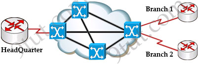
Let’s take a simple example. Suppose you are working in a big company and your company has just expanded to two new locations. The main site is connected to two branch offices, named Branch 1 & Branch 2 and your boss wants these two branches can communicate with the main site. The most simple solution is to connect them directly (called a leased line) as shown below:

To connect to these two branches, the main site router, HeadQuarter, requires two serial interfaces which a router can provide. But what happens when the company expands to 10 branches, 50 branches? For each point-to-point line, HeadQuarter needs a separate physical serial interface (and maybe a separate CSU/DSU if it is not integrated into the WAN card). As you can imagine, it will need many routers with many interfaces and lots of rack space for the routers and CSU/DSUs. Maybe we should use another solution for this problem? Luckily, Frame Relay can do it!
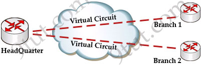
By using Frame Relay we only need one serial interface at the HeadQuarter to connect to all branches. This is also true when we expand to 10 or 50 branches. Moreover, the cost is much lesser than using leased-lines.
Frame Relay is a high-performance WAN protocol that operates at the physical and data link layers of the OSI reference model. It offers lower-cost data transfer when compared to typical point-to-point applications, by using virtual connections within the frame relay network and by combining those connections into a single physical connection at each location. Frame relay providers use a frame relay switch to route the data on each virtual circuit to the appropriate destination.
Maybe these terminologies of Frame Relay are difficult to understand so we will explain them in more detail in this article.
DCE & DTE
The first concept in Frame Relay you must grasp is about DTE & DCE:
+ Data terminal equipment (DTE), which is actually the user device and the logical Frame-relay end-system
+ Data communication equipment (DCE, also called data circuit-terminating equipment), which consists of modem and packet switch
In general, the routers are considered DTE, and the Frame Relay switches are DCE. The purpose of DCE equipment is to provide clocking and switching services in a network. In our example, HeadQuarter, Branch 1 & Branch 2 are DTEs while Frame Relay switches are DCEs.
Virtual Circuits
The logical connection through the Frame Relay network between two DTEs is called a virtual circuit (VC). The term “virtual” here means that the two DTEs are not connected directly but through a network. For example, the HeadQuarter & Branch 1 (or Branch 2) can communicate with each other as if they were directly connected but in fact they are connected through a Frame Relay network with many Frame Relay switches between them.
There are two types of VCs
+ switched virtual circuits (SVCs): are temporary connections that are only used when there is sporadic data transfer between DTE devices across the Frame Relay network. SVC is set up dynamically when needed. SVC connections require call setup and termination for each connection.
+ permanent virtual circuits (PVCs): A predefined VC. A PVC can be equated to a leased line in concept.
Nowadays most service providers offer PVC service only to save additional costs for signaling and billing procedures.


@Pijush: You can find the Frame Relay switch configuration in the Frame Relay GNS3 Lab: http://www.9tut.com/frame-relay-gns3-lab
Thanks 9tut
Are there any frame relay lab questions too in the exam?
very fantastic explanation, just like spoon feeding!
very nice study material to clear basic of frame relay
Thanks a lot for such a brilliant explanation, i recently completed my CCNA Discovery n soon to take my certification, but only after reading thia tut i v understood fram relay, so thanks 9tut. Can u plz sugest some practice exam for me, i ll b grateful.
Hi! I have a simple question, PVC states are DTE’s side or DCE’s side??
@ruban: PVC is a circuit (virtual) and not an equipment as oppose to wether it is a DTE or a DCE.
regarding the keyword “broadcast,” the definition above merely said that you can avoid split-horizon just by putting the keyword “broadcast” in the command statement?? correct me if I’m wrong, but split-horizon cannot be ignore that way. remember, a packet received on an interface cannot be transmitted over the same interface, even if the packet is received and transmitted on different virtual circuits.
@ruban
pvc r the virtual ckt from dte to dte through dce…
tht is csu/dsu or modem
Looking at your example: — you have dlci 23 twice — I know that this is possible – but isn’t it confusing? I am still confused about q7 — of the WAN section — the output shown — is not clear as to which is router A or B — I will return to that section and ask my questions there
@ruban
PVC is a circuit, meaning the actual link, although virtual, comprising the DTE and the DCE
PVC = DTE + DCE + Frame Network + DCE + DTE
@geedub
with reference to the show output stated at q7, your queue there is the DLCI 50, meaning it is in reference with Router A since DLCIs are locally significant and the ip address shown there are the remote ip add of the next hop
Thanks to giving us such a excellent example to understand about the use of Fram Relay
This is site is excellent for when I am bored at work :)
Simply and easily explained..!!
Brilliantly put together
really good notes,,,simple and understanding…thanks for such good notes
Nicely explained…thanks 9tut..
I knew that in a serial connection, one router port should have DCE and another should be DTE. So, for frame relay setup this type of clocking on one side is not reuqired I think? Can anybody please suggest? Thanks in advance.
i spend hours on google to find clearly information related frame-relay and this is definitely the best explanation i find ! top work 9tut ! keep going!!
@9tut
You are a wonder 9tut wht you are doing here is superheroe stuff you are saving the world one network admin at a time God bless u you
a lot of thanks 9tut :D
@ 9tut
I will register here at soon
* Dynamic: the router can send an Inverse ARP request to the other end of the PVC for its Layer 2 address. In short, Inverse ARP will attempt to learn its neighboring devices IP addresses and automatically create a dynamic map table. By default, physical interfaces have Inverse ARP enabled.
THere is a small mistake in this statement, its suppose to be Layer 3 address, so please dont get confuse here
Thank you so much 9tut for this tutorial i’ve learn a lot. more power 9tut.
@Mohammed Osman: Thanks for your detection. I updated it!
very easy to understant
good explanation
Is there anyway to change the VCE file format to a PDF format?
Kindly reply at earliest. Exam on March 1,2013
what cli command will use in dynacmic dlci?
very excellent but what’s the importance of the lim interface?
good explanation.
Thanks for the explanation it is superb.
Kudos!! Very good and simple explanation!
Good job thanks 9tut.
that’s true, it is well explained but it is not sufficient enough because it’s just the basic about FR. You still have something to know about frame relay…
thanks a lot
@richard but do you think it’s enough to answers frame relay questions in the ccna exam?
*to answer .. Obviously
9tut is really a tutor,very simple and precise language. i’ ve been using it and now fill confident with my preparation for next month CCNA exam.
dear readers work hard to your capability, Cisco certification pays a lot.
may 17 2013
very helpful tutorial
thank you
Today I have an exam. I am still preparing, Thank you alot for you suggestions, It was very easy to understand,
interesting thanks to 9tut
@9tut: it would be even better if you can show some configurations along with the theory.
How to get GNS3 software download? please help
I would like to practice the gns3 labs above, how to do ? need download something? please help
thanks brother
so easy tutorial