
Rapid Spanning Tree Protocol RSTP Tutorial
Note: Before reading this article you should understand how STP works. So if you are not sure about STP, please read my article about Spanning Tree Protocol tutorial first.
Rapid Spanning Tree Protocol (RSTP)
One big disadvantage of STP is the low convergence which is very important in switched network. To overcome this problem, in 2001, the IEEE with document 802.1w introduced an evolution of the Spanning Tree Protocol: Rapid Spanning Tree Protocol (RSTP), which significantly reduces the convergence time after a topology change occurs in the network. While STP can take 30 to 50 seconds to transit from a blocking state to a forwarding state, RSTP is typically able to respond less than 10 seconds of a physical link failure.
RSTP works by adding an alternative port and a backup port compared to STP. These ports are allowed to immediately enter the forwarding state rather than passively wait for the network to converge.
RSTP bridge port roles:
* Root port – A forwarding port that is the closest to the root bridge in terms of path cost
* Designated port – A forwarding port for every LAN segment
* Alternate port – A best alternate path to the root bridge. This path is different than using the root port. The alternative port moves to the forwarding state if there is a failure on the designated port for the segment.
* Backup port – A backup/redundant path to a segment where another bridge port already connects. The backup port applies only when a single switch has two links to the same segment (collision domain). To have two links to the same collision domain, the switch must be attached to a hub.
* Disabled port – Not strictly part of STP, a network administrator can manually disable a port
Now let’s see an example of three switches below:

Suppose all the switches have the same bridge priority so the switch with lowest MAC address will become root bridge -> Sw1 is the root bridge and therefore all of its ports will be Designated ports (forwarding).
Two ports fa0/0 on Sw2 & Sw3 are closest to the root bridge (in terms of path cost) so they will become root ports.
On the segment between Sw2 and Sw3, because Sw2 has lower MAC than Sw3 so it will advertise better BPDU on this segment -> fa0/1 of Sw2 will be Designated port and fa0/1 of Sw3 will be Alternative port.
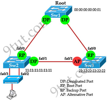
Now for the two ports connecting to the hub, we know that there will have only one Designated port for each segment (notice that the two ports fa0/2 & fa0/3 of Sw2 are on the same segment as they are connected to a hub). The other port will be Backup port according to the definition of Backup port above. But how does Sw2 select its Designated and Backup port? The decision process involves the following parameters inside the BPDU:
* Lowest path cost to the Root
* Lowest Sender Bridge ID (BID)
* Lowest Port ID
Well, both fa0/2 & fa0/3 of Sw2 has the same “path cost to the root” and “sender bridge ID” so the third parameter “lowest port ID” will be used. Because fa0/2 is inferior to fa0/3, Sw2 will select fa0/2 as its Designated port.
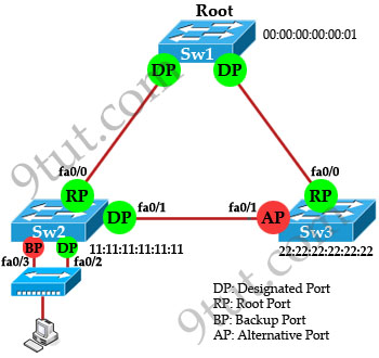
Note: Alternative Port and Backup Port are in discarding state.
RSTP Port States:
There are only three port states left in RSTP that correspond to the three possible operational states. The 802.1D disabled, blocking, and listening states are merged into the 802.1w discarding state.
* Discarding – the port does not forward frames, process received frames, or learn MAC addresses – but it does listen for BPDUs (like the STP blocking state)
* Learning – receives and transmits BPDUs and learns MAC addresses but does not yet forward frames (same as STP).
* Forwarding – receives and sends data, normal operation, learns MAC address, receives and transmits BPDUs (same as STP).
| STP State (802.1d) | RSTP State (802.1w) |
| Blocking | Discarding |
| Listening | Discarding |
| Learning | Learning |
| Forwarding | Forwarding |
| Disabled | Discarding |
Although the learning state is also used in RSTP but it only takes place for a short time as compared to STP. RSTP converges with all ports either in forwarding state or discarding state.
RSTP Quick Summary:
RSTP provides faster convergence than 802.1D STP when topology changes occur.
* RSTP defines three port states: discarding, learning, and forwarding.
* RSTP defines five port roles: root, designated, alternate, backup, and disabled.
Note: RSTP is backward compatible with legacy STP 802.1D. If a RSTP enabled port receives a (legacy) 802.1d BPDU, it will automatically configure itself to behave like a legacy port. It sends and receives 802.1d BPDUs only.


Please help
Designated ports are selected based on the lowest path cost to the root bridge for a segment. Since the root bridge will have a path cost of “0,” any ports on it that are connected to segments will become designated ports. For the other switches, the path cost is compared for a given segment. If one port is determined to have a lower path cost, it becomes the designated port for that segment. If two or more ports have the same path cost, then the switch with the lowest BID is chosen.
or
lowest root bridge id
lowest root path cost
lowest sender bridge id
lowest sender port id
So designated port are choose by lower Mac Adress or Path cost???
On scenario u choosed (designatet port SW2 (FA01) but CISCO says that
switches, the path cost is compared for a given segment. If one port is determined to have a lower path cost, it becomes the designated port for that segment. If two or more ports have the same path cost, then the switch with the lowest BID is chosen.
So please help me with this
KOWO
“Well, both fa0/2 & fa0/3 of Sw2 has the same “path cost to the root” and “sender bridge ID” so the third parameter “lowest port ID” will be used. Because fa0/2 is inferior to fa0/3, Sw2 will select fa0/2 as its Designated port.”
Small fix but:
Shouldn’t this be, “Because fa0/2 is SUPERIOR to fa0/3, Sw2 will select fa0/2 as its Designated Port”
Hi 9tut,
Thanks for your excellent updates !!!!
I have one doubt, Can you please confirm me whether root bridge is selected on basis of high bridge priority or low bridge priority.
Once more thanks for your study materials!!!! :)
Root bridge is selected based on high bridge priority(lowest value)
is there any config. command for this mode?
FYI… each interface on a bridge has a unique MAC address… see section 7.12.2 of IEEE 802.1D-2004.
hi KOWO cisco said right if you read the tutorial carefully again you will get you answer, 9tut say the same meaning
This is an excellent article. This cleared up several questions that I had on this topic. This is the kind of thing that needs to be included in the Cisco Network Academy–Lan Switching & Wireless portion. Thanks 9tut!
Thanks for your excellent updates
Great explanation!!!
Very easy to understand the concepts!!! btw, the statement “Because fa0/2 is inferior to fa0/3, Sw2 will select fa0/2 as its Designated port”, does it signifies that the number which is low becomes the DP ????
when we are choosing a root bridge, what do we check first? lower priority or lower mac address?
@India
1st – priority
first check priority regardless mac addressee value only use mac address if Priority tie
wonderfully described
awesome explanation…
Grate help … in learning
Really he;pful…
EK NUMBER
awesome explanation !!!!!!!!!! best site I ever see!!!!!!!!once again thanks
i love people taking part in this ” challenging blog”
in above case if sw 2 has lower cost path to bridge then port from sw 3 to sw 1 selected as alternate
hi!!!!
if we connect one more link between sw2 to sw3(fa0/2 to fa0/2) what will be the status of sw3 port fa0/2? backup or alternate?if administrator put port as disable manually….what is the use of that port?
gr8 explaination
Katrina
which two states are the port states when RSTP has converged ?
1. discarding
2. listening
3. learning
4. forwarding
5. disabled
please anyone explain ????
“which two states are the port states when RSTP has converged ?
1. discarding
2. listening
3. learning
4. forwarding
5. disabled
please anyone explain ????”
Maran,
Forwarding and Blocking are the two primary port states when RSTP has converged.
Simple and straight forward explanation :)
what is edge port and non-edge port in rstp ?
in between two switch any possibility of edge port ?
@Ryan.
Not totally wrong. . but when RSTP has converged the states are forwarding and ‘discarding’. Blocking is a term for ieee 802.1D common spanning tree and PVST. Blocking and discarding are almost truly synonymous, however if looking from an exam perspective, blocking would be considered a wrong answer. Also, if troubleshooting and only given partial show command that does not state RSTP as the spanning-tree mode, alternate, discarding, and blocking ports are a dead giveaway that you aren’t running 802.1D flavors of spanning tree.
to the comment above: alternate, discarding, and *****backup***** ports are a dead giveaway that you aren’t running 802.1D flavors of spanning tree.
Simple and easy to understand explanation, good work, 9tut. Thanks!