
Virtual Local Area Network VLAN Tutorial
VLAN Introduction
“A virtual LAN (VLAN) is a group of networking devices in the same broadcast domain”
It is the concept of VLAN that most of the books are using but it doesn’t help us understand the benefits of VLANs. If you ask “What is a LAN?” you will receive the same answer: it is also a group of networking devices in the same broadcast domain!
To make it clearer, I expanded the above statement into a bit longer statement :)
“A virtual LAN (VLAN) is a group of networking devices in the same broadcast domain, logically”
It means that the devices in the same VLAN may be widely separated in the network, both by geography and location. VLANs logically segment the network into different broadcast domains so that packets are only switched between ports that are designated for the same VLAN.
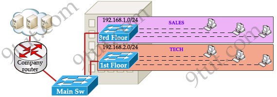
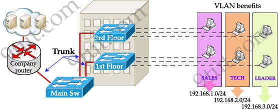
Let’s take an example to understand the benefits of VLAN. Suppose you are working in a big company with many departments, some of them are SALES and TECHNICAL departments. You are tasked to separate these departments so that each of them can only access specific resources in the company.
This task is really easy, you think. To complete this task, you just need to use different networks for these departments and use access-list to allow/deny that network to a specific resource. For example, you assign network 192.168.1.0/24 for SALES and 192.168.2.0/24 for TECH. At the “Company router” you apply an access-list to filter traffic from these networks. Below is the topology of your network without VLANs:
Everything looks good and you implement this design to your company. But after one month you receive many complaints from both your colleagues and leaders.
+ First, your department leaders need to access to additional private resources which employees are not allowed.
+ Second, the company has just recruited some new SALES employees but now the SALES room is full so they have to sit at the 1st floor (in the TECH area). They want to access to SALES resources but they can only access to the TECH resources because they are connecting to TECH switch.
To solve the first problem maybe you will create a new and more powerful network for your leaders. But notice that each leader sits at different floor so you will need to link all of them to a switch -> what a mess!
The second problem is more difficult than the first one. Maybe you have to create another network at the TECH area and apply the same policy as the SALES department for these hosts -> another mess in management!
Maybe you will be glad to know VLAN can solve all these problems. VLAN helps you group users together according to their function rather than their physical location. This means you can use the same network for hosts in different floors (of course they can communicate with each other).
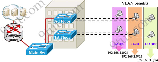
In this design:
+ you can logically create a new network with additional permissions for your leaders (LEADER network) by adding another VLAN.
+ employees can sit anywhere to access the resources in their departments, provided that you allow them to do so.
+ computers in the same department can communicate with each other although they are at different floors.
If these departments expand in the future you can still use the same network in any other floor. For example, SALES needs to have 40 more employees -> you can use 4th floor for this expansion without changing the current network.
But wait… maybe you recognize something strange in the above design? How can 2 computers connecting to 2 different switches communicate? If one computer sends a broadcast packet will it be flooded to other departments as switch doesn’t break up broadcast domains?
The answer is “Yes, they can!” and it is the beauty of VLAN. Hosts in the same VLAN can communicate normally even they are connecting to 2 or more different switches. This makes the management much more simple.
Although layer 2 switches can only break up collision domains but VLANs can be used to break up broadcast domains. So if a computer in SALES broadcasts, only computers in SALES will receive that frame.
So we don’t need a router, right? The answer is “we still need a router” to enable different VLANs to communicate with each other. Without a router, the computers within each VLAN can communicate with each other but not with any other computers in another VLAN. For example, we need a router to transfer file from LEADER to TECH. This is called “interVLAN routing”.
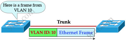
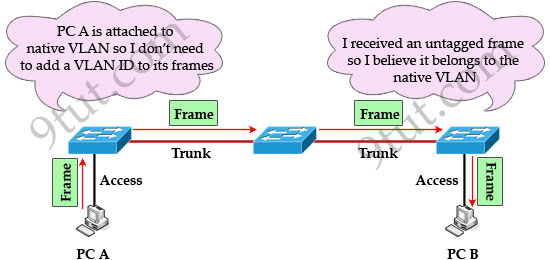
When using VLANs in networks that have multiple interconnected switches, you need to use VLAN trunking between the switches. With VLAN trunking, the switches tag each frame sent between switches so that the receiving switch knows which VLAN the frame belongs to. This tag is known as a VLAN ID. A VLAN ID is a number which is used to identify a VLAN.
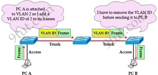
Notice that the tag is only added and removed by the switches when frames are sent out on the trunk links. Hosts don’t know about this tag because it is added on the first switch and removed on the last switch. The picture below describes the process of a frame sent from PC A to PC B.
Note: Trunk link does not belong to a specific VLAN, rather it is a conduit for VLANs between switches and routers.
To allow interVLAN routing you need to configure trunking on the link between router and switch.
Therefore in our example we need to configure 3 links as “trunk”.
Cisco switches support two different trunking protocols, Inter-Switch Link (ISL) and IEEE 802.1q. Cisco created ISL before the IEEE standardized trunking protocol. Because ISL is Cisco proprietary, it can be used only between two Cisco switches -> 802.1q is usually used in practical.
In 802.1q encapsulation, there is a concept called native VLAN that was created for backward compatibility with old devices that don’t support VLANs. Native VLAN works as follows:
+ Frame belonging to the native VLAN is not tagged when sent out on the trunk links
+ Frame received untagged on the trunk link is set to the native VLAN.
So if an old switch doesn’t support VLAN it can still “understand” that frame and continue sending it (without dropping it).
Every port belongs to at least one VLAN. If a switch receives untagged frames on a trunkport, they are assumed to be part of the native vlan. By default, VLAN 1 is the default and native VLAN but this can be changed on a per port basis by configuration.


Wonderful tutorial. Simple and efficient.
9tut, I thank you very much ;D
Crisp and to the point.. Great..
gr8 but to be as perfect as expected from 9tut we could talk a little bit more about inter vlan routing
Another good piece of work. Your works are well appreciated by many like me, 9tut. May God bless you !!!
Thanks 9tut,
Impresive…easy to understand..
very super explanation
Great Job. Keep it up. 9tut rocks!!!
Thank u Very much, easy method for new lerners about VLN
Thanks, It is very great help to understand the topic over the VLAN. I assume books could not be able to provide such practical and understandable instances.
thanks a ton !!! superb explanation ..!!
very good one thanks 9tut
I have a question on the first figure. If you design it such that there are 2 switches (for sales and tech) then those 2 connect to a Main switch, shouldn’t you already configure the Main Switch to use 2 VLAN’s for it to work? Because the last statement before that figure is:
Below is the topology of your network without VLANs. If the topology included two switches connected directly to the router, I would understand that it is a network without VLAN’s.
I just passed ICND1 so I am new to this.
Upon studying it further (and correct me if I am wrong), it is in fact a topology without VLAN’s. Sales and Tech belong to their VLAN 1 and Main Switch to its VLAN 1.
within the same VTP domain you can assign ports to VLANs.
if you had 3 different VTP domains then… ok, you could use 3 VLAN1s.
each VLAN is unique within a VTP domain.
Hey Xallax, it’s you! I was trying that topology on PT. Referring on the first figure, so I have Sales connected to 3 host and Tech also with 3. Sales is .1.0 and Tech is .2.0 so I would have no problem configuring the PC with an IP address and subnet mask. But what would be it’s default gateway then? And how do I configure Main Switch? Say Sales is connected to fa 0/0 of Main and Tech on fa 0/1, how do I configure Main Switch? Again, I say this because the tutorial said it is a topology WITHOUT Vlan’s. I wouldn’t have a problem if Sales and Tech was connected directly to the router. But the presence of the Main Switch means that in order for the topology to function, VLAN’s would be incorporated.
you have a router: R1
configuration:
interface fa0/0.1 192.168.1.1 255.255.255.0
interface fa0/0.2 192.168.2.1 255.255.255.0
interface fa0/0.3 192.168.3.1 255.255.255.0
we need those subinterfaces because we have to route for 3 LANs on the same interface (a VLAN is a… LAN)
go to the main switch
the interfaces to R1 and other switches should be configured to operate as trunk
interface x/x
switchport mode trunk
set the VTP domain, set the VTP mode, the VTP password (if you want to), set this to be in server mode (default)
create the required VLANs
vlan 10
name this-is-vlan-10
no shutdown
go to the Access Layer switches and configure the access ports (ports where the PCs connect) to be in the corresponding VLAN
interface fa x/x
switchport access vlan #
hope this helps, welcome to the ICND2 preparation forums jeff :)
forgot this: configure the same VTP domain name, mode and password on all other switches
Switch>enable
Switch#configure terminal
Switch(config)#vtp domain Test
Switch(config)#vtp version 2
Switch(config)#vtp password 1234
I don’t understand the trunk and VTP yet. Just beginning to learn VLANs. But based on what I see, you used the word trunk and VTP which suggest that in order for the topology to work, you need to incorporate VLANs. I mean if Sales and Tech directly connected to a router interface, I won’t even need to configure anything on the those switches and it would work. But the presence of a Main Switch changes everything. I guess what I am trying to say is it is a topology with VLANs and not without VLANs.
I’d be in here a lot. ICND2 seems much, much more interesting than ICND1.
VTP = VLAN Trunking Protocol
it’s cisco’s way of making switch management easier.
VTP works this way:
servers update other servers and clients (based on revision number – how may times the database was modified). servers pass updates
clients update their database if advertised revision number is greater than the current on. they also pass updates
transparent mode switches have their own vlan database, but they pass the updates.
all switches participating in the VTP domain must have the same domain name, vtp version (1 or 2) and password.
access link: only 1 vlan information goes through here (usually from hosts or printers)
trunk link: info from several VLANs passes through here. the alternative would’ve been having one access link for each VLAN, that would’ve been insane.
best exercise:
add 3 switches and configure the VTP on one of them, create a few VLANs. move to the other 2 and set only the domain name to match the one on the first switch.
Switch# show vlan brief
you will see the VLANs configured on the first switch appearing on the other 2.
But do you agree that it is a topology with VLANs and not without VLANs? That is the main point I was raising.
This site should have a chat or who’s online thing on it. It would be a great addition.
no, you need VLANs here.
let me build it in PT, i will post here the command strings
Thank you. That was the part I was mostly concerned about. You need to incorporate VLANs on that topology. But without a Main switch, you wouldn’t have to.
that switch is at the distribution level, it connects ALL the switches to the router.
imagine you had 30 switches with 24 ports each in your huge company.
you would connect the access switches (those to which hosts connect) to distribution switches that connect to the router.
I would probably learn that as I go along. But the point is that it is a topology with VLANs. The tutorial then becomes kind of “misleading”. I actually stopped reading after I saw the line “Below is the topology of your network without VLANs:” and looked at the topology because there shouldn’t be a Main Switch there for it to be a topology without VLANs. I started posting to clear it out and xallax is always there to the rescue.
@Jeff2: In theory, if we don’t use VLANs then we don’t need to use the “Main Switch” there. But for some management reasons, you still need to use it. For example, your company has 30 switches (as xallax mentioned above), without the “Main Switch” you need 30 interfaces on the routers! So some administrators can decide to use the “Main Switch” from the beginning.
I understand the need for the Main Switch. But given that topology with the Main Switch (first figure), it was specified that it is a network topology *without* VLANs when in fact you would need VLAN’s for it to work. Let’s say a host from sales pings the company router successfully, how would you configure the Main Switch *without* VLANs for it to work? You can’t, right?
yep, you’re right jeff. we need vlans here
here’s the link to the topology
http://www.mediafire.com/?wfgwa22dnab87n3
do a “sh run” on the router and the switches to see the commands i’ve applied. feel free to ask anything about the setup, i’ll reply asap
Thanks Xallax. I don’t have anything to comment about the setup yet as I don’t know any of those “new” commands. I am still understanding the VLAN concepts part. I’ll get back to it once I’ve familiarized myself with VLANs and VTP.
Just a quick question though, what would happen if I configure Sales switch as VLAN 1 and Tech switch also for VLAN 1. Is that gonna be a problem? I mean they are on different switches. Then just configure them on their Main Switch connection.
I think you can’t. I looked at the router and noticed the 0.10 and 0.20 which I suppose means VLAN 10 and VLAN 20. So you can’t have 2 VLAN 1s, right? Thanks again Xallax.
@Jeff2: We can use the command “ip default-gateway {IP address}” on “Main Switch” to send traffic from the “Main Switch” to the router. With this command, if a switch doesn’t know where to send the traffic, it will send to that IP.
@xallax
I just finished the VLAN videos by cbtnuggets. I now understand the commands you made for that topology. My question is, by effectively creating those sub-interfaces on your router, then the VLAN’s can now communicate! Now how do you fix that? It’s probably another topic on the ICND2 series but I want to know what that is.
@jeff
you create the subinterfaces (it doesnt matter what number they are)
you set the encapsulation and the vlan for which the act as default gateways
you configure them each with an IP
that’s it
But by doing that, now those VLANs can communicate. Sales can ping Tech. Now what was the whole point of putting them on separate VLANs?
@jeff
easier management. it’s like putting files into folders. why do you do that? because you want texts about icnd1 in one folder and pictures of funny animals in another folder.
say you want to have a vlan for the employes, a vlan for secretarial works, a vlan for the bosses, a vlan for security team, a vlan for IT, a vlan for computer security…
it would’ve been a pain to monitor all those computers if you hadnt had vlans.
further more, you can allow only certain vlans to talk to each other. you don’t want the rest of the world to access the bosses vlan, do you?
vlans are what subnetting is about when you do it in a switched LAN.
to elaborate the “can allow only certain vlans to talk to each other” statement:
vlans go hand in hand with access-lists. a vlan is a block of IPs and it’s far easier to use a wildcard mask and to implement an access-list to deny or permit traffic from one point to another on your network.
this is yet another tiny piece of the ICND2 puzzle that you must master. you came a long way from the point you knew nothing about internetworks jeff. you should be proud of this.
I really wish we can chat. I understand what VLANs is for. Again, focusing on the topology for the first figure, you configured a default gateway for sales and tech on the router that would now enable Sales to talk to Tech. (Btw, I already know how to configure vlans, vtp and router on a stick). Now how do I limit communication only between Sales and only between Tech WITH router on a stick enabled? I am confused because when you enable routing between VLAN’s, then you kind of “disable” VLANs because now they can talk to each other.
Oh wait, you posted the access-list thing. Maybe that would answer my question. I am on STP at the moment. Thanks for the help again xallax.
im here to help :)
there’s a little picture on my site that pops up a yahoo messenger window and starts a chat with me :) (provided that you have yahoo messenger installed of cource)
http://www.tinyurl.com/xallaxvce
I’d go there once in a while. You seem to be online a lot. I am trying to learn ICND2 a little faster and go for the exam (hopefully) in the first week of October.
it’s summer break over here till october 1st.
more time for my little website project :)
I am on access lists now xallax. I’ve now created an extended access lists so sales and tech cannot reach each other even with router on a stick working. Managed to configure dhcp for multiple vlans too. Too bad I don’t know how to simulate TCP and UDP for extended ACLs.
@jeff2
telnet works on tcp
dhcp (client-side) works on udp
try with those
forgot about telnet. again, xallax to the rescue.
it’s highly needed a vtp tutorial dear xallax..u r doin things great..keep it up
@triple-x
let’s hope the owner of 9tut will create one or…
maybe i can contribute on that too, i don’t know, kinda stressed out on free time at the moment. this will be a long week with so many planed.
i’ll keep it in mind :)
thanx a lot….
@triple-x
you can always go here to read a few things regarding vtp :)
http://www.mcmcse.com/cisco/guides/vtp.shtml
@triple-x
you know… there is a VTP tutorial already posted here…
http://www.9tut.com/vlan-trunk-protocol-vtp-tutorial
Very usfel information and discussion, keep it up and alive.
Thanks
Again a very nice tutorial from 9tut and a great discussion here in the comment section.
Thanks everyone :)