
Virtual Local Area Network VLAN Tutorial
VLAN Introduction
“A virtual LAN (VLAN) is a group of networking devices in the same broadcast domain”
It is the concept of VLAN that most of the books are using but it doesn’t help us understand the benefits of VLANs. If you ask “What is a LAN?” you will receive the same answer: it is also a group of networking devices in the same broadcast domain!
To make it clearer, I expanded the above statement into a bit longer statement :)
“A virtual LAN (VLAN) is a group of networking devices in the same broadcast domain, logically”
It means that the devices in the same VLAN may be widely separated in the network, both by geography and location. VLANs logically segment the network into different broadcast domains so that packets are only switched between ports that are designated for the same VLAN.
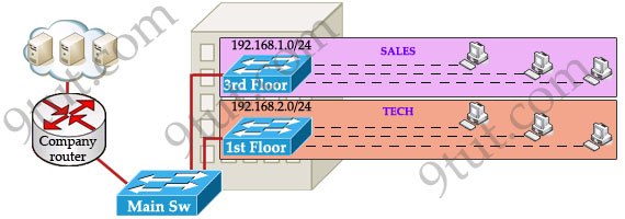
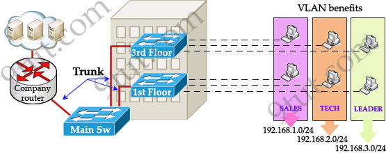
Let’s take an example to understand the benefits of VLAN. Suppose you are working in a big company with many departments, some of them are SALES and TECHNICAL departments. You are tasked to separate these departments so that each of them can only access specific resources in the company.
This task is really easy, you think. To complete this task, you just need to use different networks for these departments and use access-list to allow/deny that network to a specific resource. For example, you assign network 192.168.1.0/24 for SALES and 192.168.2.0/24 for TECH. At the “Company router” you apply an access-list to filter traffic from these networks. Below is the topology of your network without VLANs:
Everything looks good and you implement this design to your company. But after one month you receive many complaints from both your colleagues and leaders.
+ First, your department leaders need to access to additional private resources which employees are not allowed.
+ Second, the company has just recruited some new SALES employees but now the SALES room is full so they have to sit at the 1st floor (in the TECH area). They want to access to SALES resources but they can only access to the TECH resources because they are connecting to TECH switch.
To solve the first problem maybe you will create a new and more powerful network for your leaders. But notice that each leader sits at different floor so you will need to link all of them to a switch -> what a mess!
The second problem is more difficult than the first one. Maybe you have to create another network at the TECH area and apply the same policy as the SALES department for these hosts -> another mess in management!
Maybe you will be glad to know VLAN can solve all these problems. VLAN helps you group users together according to their function rather than their physical location. This means you can use the same network for hosts in different floors (of course they can communicate with each other).
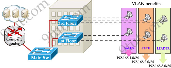
In this design:
+ you can logically create a new network with additional permissions for your leaders (LEADER network) by adding another VLAN.
+ employees can sit anywhere to access the resources in their departments, provided that you allow them to do so.
+ computers in the same department can communicate with each other although they are at different floors.
If these departments expand in the future you can still use the same network in any other floor. For example, SALES needs to have 40 more employees -> you can use 4th floor for this expansion without changing the current network.
But wait… maybe you recognize something strange in the above design? How can 2 computers connecting to 2 different switches communicate? If one computer sends a broadcast packet will it be flooded to other departments as switch doesn’t break up broadcast domains?
The answer is “Yes, they can!” and it is the beauty of VLAN. Hosts in the same VLAN can communicate normally even they are connecting to 2 or more different switches. This makes the management much more simple.
Although layer 2 switches can only break up collision domains but VLANs can be used to break up broadcast domains. So if a computer in SALES broadcasts, only computers in SALES will receive that frame.
So we don’t need a router, right? The answer is “we still need a router” to enable different VLANs to communicate with each other. Without a router, the computers within each VLAN can communicate with each other but not with any other computers in another VLAN. For example, we need a router to transfer file from LEADER to TECH. This is called “interVLAN routing”.
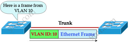
When using VLANs in networks that have multiple interconnected switches, you need to use VLAN trunking between the switches. With VLAN trunking, the switches tag each frame sent between switches so that the receiving switch knows which VLAN the frame belongs to. This tag is known as a VLAN ID. A VLAN ID is a number which is used to identify a VLAN.
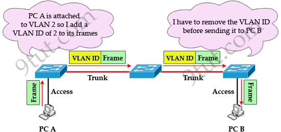
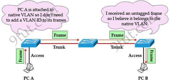
Notice that the tag is only added and removed by the switches when frames are sent out on the trunk links. Hosts don’t know about this tag because it is added on the first switch and removed on the last switch. The picture below describes the process of a frame sent from PC A to PC B.
Note: Trunk link does not belong to a specific VLAN, rather it is a conduit for VLANs between switches and routers.
To allow interVLAN routing you need to configure trunking on the link between router and switch.
Therefore in our example we need to configure 3 links as “trunk”.
Cisco switches support two different trunking protocols, Inter-Switch Link (ISL) and IEEE 802.1q. Cisco created ISL before the IEEE standardized trunking protocol. Because ISL is Cisco proprietary, it can be used only between two Cisco switches -> 802.1q is usually used in practical.
In 802.1q encapsulation, there is a concept called native VLAN that was created for backward compatibility with old devices that don’t support VLANs. Native VLAN works as follows:
+ Frame belonging to the native VLAN is not tagged when sent out on the trunk links
+ Frame received untagged on the trunk link is set to the native VLAN.
So if an old switch doesn’t support VLAN it can still “understand” that frame and continue sending it (without dropping it).
Every port belongs to at least one VLAN. If a switch receives untagged frames on a trunkport, they are assumed to be part of the native vlan. By default, VLAN 1 is the default and native VLAN but this can be changed on a per port basis by configuration.


thaks all for nice advice.
Can you please send me the latest dump of questions for the CCNA exams?
I will be taking my certification exam early next year.
Thank you so much! 9tut is such a great place to learn! – abrahamgoc@yahoo.com
Thanks, this tutorial of VLAN is easy to learn.
I don’t really understand about ‘trunking’ word before read this article
thanks, awesome tutorial.. i really don;t get how yo do vlan at first.. thanks again :)
Thanks.. I think I understand better for my exam :D
@xallax
Hello. I’ve passed ICND1. Thank you and 9tut.
I have a question: I think you know that on real routers we can assign two or more IP addresses on one physical interface (e.g ip addr 192.168.1.1/24, ip addr 192.168.10.1/24 sec)
For what purposes it is used?
If we can assign more than one ip address on one router’s interface, why we need VLAN’s in this example task?
We attached new sales employees in TECH department. We assign to their computers IP adresses and default gateway from SALES scope. Because our router has two IP adresses on one interface, it can route traffic from both departments (first IP for TECH and second IP for SALES)
Where are difficults?
Yes, I understand that VLAN’s decrease broadcast size and increase its amount, it reduce worthless chanel’s bandwidth using. But I don’t fully understand the meaning VLAN using for security and scalability…If it is not difficult for you, could you explain me two approaches to network creating in this case: without VLAN using and using VLANs.
@anonymous
using secondary addresses is like using subinterfaces. all routers that are directly connected must have IP addresses on the same secondary subnets too. kinda like subinterfaces…
why do VLANs increase security? because you can assign, for example, computers from IT to a subnet of /29, computers from Finance to a subnet of /29, computers from the offices to a subnet of /25.
this way computers from one department dont get to communicate with computers from another department without sending traffic to the default gateway (which is a L3 device) first. what’s the beauty of L3 devices? they enforce security via access lists.
and that’s how VLANs provide increased security :)
actually… the thing about VLANs is not about the router, is about the switch. at the LAN level you know that 1 or some routers do the routing, but the switches are the work horses that send frames towards their destination.
VLANs are good to categorize the devices that connect at the access layer, VTP is good to propagate/maintain that nice structure you’ve created
thanks 9tut! very well discussed!
this is what called tutorials
Very useful thank you
nice tutorial,
useful indeed!!
where can i find complete tutorial notes links¿?
I can only seeexam questions linked!
Thanks amazingggg site
@jesullrov: You can find all my tutorials here: http://www.9tut.com/category/ccna-knowledge
How would stacked switches play into this? Say I had several switches in a stack all linked together. This topology continues in several buildings that all need to be linked to a central site through a core switch. How should I go about assigning several different vlans for several different broadcast domains and still have them communcate with who needs it. Would it be better to make the master switch in each stack a layer 3 switch to route between vlan’s in each switch stack or send all traffic back to core switch to be routed. Could stacking cables also be used for trunking vlans together?
@9tut
1st_Floor_Switch(config)#interface f0/0
1st_Floor_Switch(config-if)#switchport access vlan 2
1st_Floor_Switch(config-if)#interface f0/1
1st_Floor_Switch(config-if)#switchport access vlan 3
is there fa0/0 in a switch?
9tut , thank you very much
you’ve done a great work
^_^
It’s a great website to networkers
nice explanation…………..
awesome explanation………………..
Very nice tutorials. Keep it up, please…….
Yes, I agree, it is really good explanation….
simple to understand…..
nice explanation
Nicely composed ,Indeed.
send me latest dumps on tshons@gmx.com
send me latest dumps on andymunoz@hotmail.com
Thx
Thanks for the explanation
I will be taking CCNA certification exam early next year.Can you please send me the latest dump of questions for that.
Please send the dump to my mail id:::: tmi12345@yahoo.com
Thanks
send me latest ccnp switching dumps dhinas.dreams@gmail.com
your are missing which interface select the vlan trunk in upper configuration
hanks.. I think I understand better for my exam :D
Dear
every body can send me
CCNA dumps who latest and give me one chance thanks
Dear
every body can send me
CCNA dumps who latest and give me one chance thanks
Ghayyur218@hotmail.com
I just wanted to compliment you on your tutorial. It is one of the better ones I have come across. Your illustrations and examples are very helpful and easy to understand. I am not going for the CCNA or anything else. I was just interested in what a VLAN was and why you would want to use one; and now I know:))
Thanks!!
please send me latest dumps to saravanas619@gmail.com ,im in uk ,preparing for my ccna ,ve to write it with in 4 mnts ,need ur help desperately ..will uuuuuuuuu
I have not read yet all. but i think i can gain more from this site.
please send me the latest dumps psstockinfo@gmail.com
thanks
ITS REALLY INFORMATIVE SITE!
CAN YOU SEND ME THE CONFIG OF VLAN AND INTER-VLAN
UMARBILAL@UCP.EDU.PK
I like VLAN implementation, thanks of the information on this page.
There are two machines on a LAN. How can I configure a VLAN between the two? I tried giving the same vlan id to both and used ifconfig to create an interface on both machines
Nice. Also explain about VTP pruning.
send me ccna dumps please collinsjumaz42@gmail.com
i will read all pages to get my CCNA certification !!!!!!! realy it’s too gooddddd
Posted on If they add the Fibre SFP to the gigabit stcwih port group the RB2011 could make an amazing customer house network termination unit in my opinion. Currently any decent stcwih with vlans + troubleshooting features is $500-1000 for even a 12~ port model when quite often all that is needed (for us anyway) is 1 fibre for the line in, 1 port for a Wireless or ADSL backup and then some ports for the customer router
Hi Ryan,You have a mis-configuration between the two VRRP rorteus. You probably have Fast Advertisement enabled on one but disabled on the other. Assuming that your VRIDs match your VLAN IDs you could issue the following command on both your ERS 8600 switches;ERS-8610:5# config vlan 8 ip vrrp 8 infoSub-Context: clear config dump monitor show test trace wsm asfm samCurrent Context: action : none address : IP ADDRESS OF VRRP INTERFACE adver-int : 1 backup-master : enable critical-ip : 0.0.0.0 critical-ip-enable : disable fast-adv-int : 200 fast-adv-enable : disable delete : N/A vrrp enable : enable holddown-timer : 0 priority : 100The settings should be identical on both ERS 8600 switches. It sounds to me like someone has enabled Fast Advertisement on one of the switches but left it disabled on the other switch. Just go ahead and disable Fast Advertisement (fast-adv-enable) and the error should clear.Good Luck!
Hi Michael,th naks for reply the voice vlan is 25 and the port which the ip phone is connected is 5 the dhcp is glabolly define on the server and connected on the l3 switchi have recived the logs on the switch is mentioned below 4826GTS-PWR+(config)#show logging Type Time Idx Src Message – – – I 00:00:39:25 108 Link Down Trap for Port: 5 I 00:00:39:30 109 Link Down Trap for Port: 23 I 00:00:39:32 110 Trap: pethPsePortOnOffNotification I 00:00:39:32 111 PoE Port Detection Status: Port 5 Status: Detecting I 00:00:39:33 112 Link Up Trap for Port: 24 I 00:00:39:36 113 Trap: pethPsePortOnOffNotification I 00:00:39:36 114 PoE Port Detection Status: Port 5 Status: Delivering Power I 00:00:39:40 115 Link Down Trap for Port: 24 I 00:00:39:43 116 Link Up Trap for Port: 23 I 00:00:39:53 117 Link Up Trap for Port: 5 I 00:00:40:18 118 Trap: bsnConfigurationSavedToNvram I 00:00:41:28 119 Trap: lldpXMedTopologyChangeDetect ed, Subtype = 5 Class = 3 I 00:00:41:29 120 Trap: lldpRemTableChange Inserts = 18 I 00:00:42:04 121 Link Down Trap for Port: 5 I 00:00:42:28 122 Link Up Trap for Port: 5 4826GTS-PWR+(config)# 4826GTS-PWR+(config)#show logging Type Time Idx Src Message – – – I 00:00:39:25 108 Link Down Trap for Port: 5 I 00:00:39:30 109 Link Down Trap for Port: 23 I 00:00:39:32 110 Trap: pethPsePortOnOffNotification I 00:00:39:32 111 PoE Port Detection Status: Port 5 Status: Detecting I 00:00:39:33 112 Link Up Trap for Port: 24 I 00:00:39:36 113 Trap: pethPsePortOnOffNotification I 00:00:39:36 114 PoE Port Detection Status: Port 5 Status: Delivering Power I 00:00:39:40 115 Link Down Trap for Port: 24 I 00:00:39:43 116 Link Up Trap for Port: 23 I 00:00:39:53 117 Link Up Trap for Port: 5 I 00:00:40:18 118 Trap: bsnConfigurationSavedToNvram I 00:00:41:28 119 Trap: lldpXMedTopologyChangeDetect ed, Subtype = 5 Class = 3 I 00:00:41:29 120 Trap: lldpRemTableChange Inserts = 18 I 00:00:42:04 121 Link Down Trap for Port: 5 I 00:00:42:28 122 Link Up Trap for Port: 5 4826GTS-PWR+(config)#show logging Type Time Idx Src Message – – – I 00:00:39:25 108 Link Down Trap for Port: 5 I 00:00:39:30 109 Link Down Trap for Port: 23 I 00:00:39:32 110 Trap: pethPsePortOnOffNotification I 00:00:39:32 111 PoE Port Detection Status: Port 5 Status: Detecting I 00:00:39:33 112 Link Up Trap for Port: 24 I 00:00:39:36 113 Trap: pethPsePortOnOffNotification I 00:00:39:36 114 PoE Port Detection Status: Port 5 Status: Delivering Power I 00:00:39:40 115 Link Down Trap for Port: 24 I 00:00:39:43 116 Link Up Trap for Port: 23 I 00:00:39:53 117 Link Up Trap for Port: 5 I 00:00:40:18 118 Trap: bsnConfigurationSavedToNvram I 00:00:41:28 119 Trap: lldpXMedTopologyChangeDetect ed, Subtype = 5 Class = 3 I 00:00:41:29 120 Trap: lldpRemTableChange Inserts = 18 I 00:00:42:04 121 Link Down Trap for Port: 5 I 00:00:42:28 122 Link Up Trap for Port: 5 I 00:00:44:04 123 Trap: lldpXMedTopologyChangeDetect ed, Subtype = 5 Class = 3 I 00:00:44:04 124 Trap: lldpRemTableChange Inserts = 19 I 00:00:44:43 125 Link Down Trap for Port: 5 I 00:00:45:07 126 Link Up Trap for Port: 5 I 00:00:46:39 127 Trap: lldpXMedTopologyChangeDetect ed, Subtype = 5 Class = 3 I 00:00:46:39 128 Trap: lldpRemTableChange Inserts = 20 I 00:00:47:15 129 Link Down Trap for Port: 5 I 00:00:47:40 130 Link Up Trap for Port: 5 I 00:00:48:41 131 Trap: lldpXMedTopologyChangeDetect ed, Subtype = 5 Class = 3 I 00:00:48:44 132 Trap: lldpRemTableChange Inserts = 21 I 00:00:49:08 133 Link Down Trap for Port: 5 I 00:00:49:33 134 Link Up Trap for Port: 5 I 00:00:50:33 135 Trap: lldpXMedTopologyChangeDetect ed, Subtype = 5 Class = 3 I 00:00:50:34 136 Trap: lldpRemTableChange Inserts = 22 I 00:00:51:02 137 Trap: lldpXMedTopologyChangeDetect ed, Subtype = 5 Class = 3 I 00:00:51:04 138 Link Down Trap for Port: 5 I 00:00:51:04 139 Trap: lldpRemTableChange Inserts = 23 I 00:00:51:28 140 Link Up Trap for Port: 5 I 00:00:52:59 141 Trap: lldpXMedTopologyChangeDetect ed, Subtype = 5 Class = 3 I 00:00:52:59 142 Trap: lldpRemTableChange Inserts = 24 I 00:00:53:38 143 Link Down Trap for Port: 5 I 00:00:54:03 144 Link Up Trap for Port: 5 I 00:00:55:04 145 Trap: lldpXMedTopologyChangeDetect ed, Subtype = 5 Class = 3 I 00:00:55:04 146 Trap: lldpRemTableChange Inserts = 25 I 00:00:55:31 147 Link Down Trap for Port: 5 I 00:00:55:55 148 Link Up Trap for Port: 5 I 00:00:56:57 149 Trap: lldpXMedTopologyChangeDetect ed, Subtype = 5 Class = 3 I 00:00:56:59 150 Trap: lldpRemTableChange Inserts = 26 I 00:00:57:24 151 Link Down Trap for Port: 5 4826GTS-PWR+(config)# 4826GTS-PWR+(config)# 4826GTS-PWR+(config)# 4826GTS-PWR+(config)# 4826GTS-PWR+(config)# 4826GTS-PWR+(config)# 4826GTS-PWR+(config)#set p 4826GTS-PWR+(config)#set p 4826GTS-PWR+(config)#set p 4826GTS-PWR+(config)#set p 4826GTS-PWR+(config)#set p 4826GTS-PWR+(config)#set pO 4826GTS-PWR+(config)#set pO 4826GTS-PWR+(config)#set pO 4826GTS-PWR+(config)#set pO 4826GTS-PWR+(config)#? Configure commands: adac Modify ADAC settings arp Configure a static ARP entry asset-id Configure the Asset-ID audit Enable audit log save settings auto-pvid Enable Auto-PVID (for all ports). autosave Change autosave settings autotopology Enable the autotopology protocol banner Set custom banner info cli Modify password settings clock Global RTC configuration subcommands default Set a command to its defaults eapol Enable/disable EAPOL protocol. edm Modify EDM settings end Exit from configure mode energy-saver Configure global energy saver settings exit Exit from configure mode http-port Set the TCP port on which web server will listen interface Select an interface to configure ip Global IP configuration subcommands ipmgr Modify IP Manager settings. ipv6 Global IPv6 configuration subcommands 4826GTS-PWR+(config)#SHOPW LOGG 4826GTS-PWR+(config)#SHOW LOGG 4826GTS-PWR+(config)#SHOW LOGGing Type Time Idx Src Message – – – I 00:00:39:25 108 Link Down Trap for Port: 5 I 00:00:39:30 109 Link Down Trap for Port: 23 I 00:00:39:32 110 Trap: pethPsePortOnOffNotification I 00:00:39:32 111 PoE Port Detection Status: Port 5 Status: Detecting I 00:00:39:33 112 Link Up Trap for Port: 24 I 00:00:39:36 113 Trap: pethPsePortOnOffNotification I 00:00:39:36 114 PoE Port Detection Status: Port 5 Status: Delivering Power I 00:00:39:40 115 Link Down Trap for Port: 24 I 00:00:39:43 116 Link Up Trap for Port: 23 I 00:00:39:53 117 Link Up Trap for Port: 5 I 00:00:40:18 118 Trap: bsnConfigurationSavedToNvram I 00:00:41:28 119 Trap: lldpXMedTopologyChangeDetect ed, Subtype = 5 Class = 3 I 00:00:41:29 120 Trap: lldpRemTableChange Inserts = 18 I 00:00:42:04 121 Link Down Trap for Port: 5 I 00:00:42:28 122 Link Up Trap for Port: 5 I 00:00:44:04 123 Trap: lldpXMedTopologyChangeDetect ed, Subtype = 5 Class = 3 I 00:00:44:04 124 Trap: lldpRemTableChange Inserts = 19 I 00:00:44:43 125 Link Down Trap for Port: 5 I 00:00:45:07 126 Link Up Trap for Port: 5 I 00:00:46:39 127 Trap: lldpXMedTopologyChangeDetect ed, Subtype = 5 Class = 3 I 00:00:46:39 128 Trap: lldpRemTableChange Inserts = 20 I 00:00:47:15 129 Link Down Trap for Port: 5 I 00:00:47:40 130 Link Up Trap for Port: 5 I 00:00:48:41 131 Trap: lldpXMedTopologyChangeDetect ed, Subtype = 5 Class = 3 I 00:00:48:44 132 Trap: lldpRemTableChange Inserts = 21 I 00:00:49:08 133 Link Down Trap for Port: 5 I 00:00:49:33 134 Link Up Trap for Port: 5 I 00:00:50:33 135 Trap: lldpXMedTopologyChangeDetect ed, Subtype = 5 Class = 3 I 00:00:50:34 136 Trap: lldpRemTableChange Inserts =
I have not read yet all but i will gain all the explanation about VLAN nd easy to undrestand thanks….
thanks ;)
cheers man.. that was awesum !!