
CCNA Implementation SIM
This topology contains 3 routers and 1 switch. Complete the topology.
Drag the appropriate device icons to the labeled Device
Drag the appropriate connections to the locations labeled Connections.
Drag the appropriate IP addresses to the locations labeled IP address
(Hint: use the given host addresses and Main router information)
To remove a device or connection, drag it away from the topology.
Use information gathered from the Main router to complete the configuration of any additional routers. No passwords are required to access the Main router. The config terminal command has been disabled for the HQ router. The router does not require any configuration.
Configure each additional router with the following:
Configure the interfaces with the correct IP address and enable the interfaces.
Set the password to allow console access to consolepw
Set the password to allow telnet access to telnetpw
Set the password to allow privilege mode access to privpw
Note: Because routes are not being added to the configurations, you will not be able to ping through the internetwork.
All devices have cable autosensing capabilities disabled.
All hosts are PC’s

Answer and explanation
Note: You can download this sim to practice here: http://www.9tut.com/download/9tut.com_CCNA_Implementation_question.zip
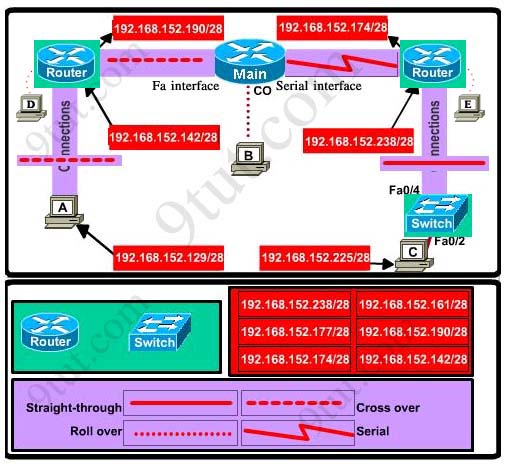
Specify appropriate devices and drag them on the “Device” boxes
For the device at the bottom-right box, we notice that it has 2 interfaces Fa0/2 and Fa0/4; moreover the link connects the PC on the right with the device on the bottom-right is a straight-through link -> it is a switch
The question stated that this topology contains 3 routers and 1 switch -> two other devices are routers
Place them on appropriate locations as following:

(Host D and host E will be automatically added after placing two routers. Click on them to access neighboring routers)
Specify appropriate connections between these devices:
+ The router on the left is connected with the Main router through FastEthernet interfaces: use a crossover cable
+ The router on the right is connected with the Main router through Serial interfaces: use a serial cable
+ The router on the right and the Switch: use a straight-through cable
+ The router on the left and the computer: use a crossover cable
(To remember which type of cable you should use, follow these tips:
- To connect two serial interfaces of 2 routers we use serial cable
– To specify when we use crossover cable or straight-through cable, we should remember:
Group 1: Router, Host, Server
Group 2: Hub, Switch
One device in group 1 + One device in group 2: use straight-through cable
Two devices in the same group: use crossover cable
For example: we use straight-through cable to connect switch to router, switch to host, hub to host, hub to server… and we use crossover cable to connect switch to switch, switch to hub, router to router, host to host… )

Assign appropriate IP addresses for interfaces:
From Main router, use show running-config command:
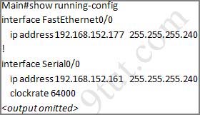
(Notice that you may see different IP addresses in the real CCNA exam, the ones shown above are just used for demonstration)
From the output we learned that the ip address of Fa0/0 interface of the Main router is 192.168.152.177/28. This address belongs to a subnetwork which has:
Increment: 16 (/28 = 255.255.255.240 or 1111 1111.1111 1111.1111 1111.1111 0000)
Network address: 192.168.152.176 (because 176 = 16 * 11 and 176 < 177)
Broadcast address: 192.168.152.191 (because 191 = 176 + 16 – 1)
And we can pick up an ip address from the list that belongs to this subnetwork: 192.168.152.190 and assign it to the Fa0/0 interface the router on the left
Use the same method for interface Serial0/0 with an ip address of 192.168.152.161
Increment: 16
Network address: 192.168.152.160 (because 160 = 16 * 10 and 160 < 161)
Broadcast address: 192.168.152.175 (because 176 = 160 + 16 – 1)
-> and we choose 192.168.152.174 for Serial0/0 interface of the router on the right
Interface Fa0/1 of the router on the left
IP (of the computer on the left) : 192.168.152.129/28
Increment: 16
Network address: 192.168.152.128 (because 128 = 16 * 8 and 128 < 129)
Broadcast address: 192.168.152.143 (because 143 = 128 + 16 – 1)
-> we choose 192.168.152.142 from the list
Interface Fa0/0 of the router on the right
IP (of the computer on the left) : 192.168.152.225/28
Increment: 16
Network address: 192.168.152.224 (because 224 = 16 * 14 and 224 < 225)
Broadcast address: 192.168.152.239 (because 239 = 224 + 16 – 1)
-> we choose 192.168.152.238 from the list
Let’s have a look at the picture below to summarize
Configure two routers on the left and right with these commands:
Router1 = router on the left
Assign appropriate IP addresses to Fa0/0 & Fa0/1 interfaces:
Router1>enable
Router1#configure terminal
Router1(config)#interface fa0/0
Router1(config-if)#ip address 192.168.152.190 255.255.255.240
Router1(config-if)#no shutdown
Router1(config-if)#interface fa0/1
Router1(config-if)#ip address 192.168.152.142 255.255.255.240
Router1(config-if)#no shutdown
Set passwords (configure on two routers)
+ Console password:
Router1(config-if)#exit
Router1(config)#line console 0
Router1(config-line)#password consolepw
Router1(config-line)#login
Router1(config-line)#exit
+ Telnet password:
Router1(config)#line vty 0 4
Router1(config-line)#password telnetpw
Router1(config-line)#login
Router1(config-line)#exit
+ Privilege mode password:
Router1(config)#enable password privpw
Save the configuration:
Router1(config)#exit
Router1#copy running-config startup-config
Configure IP addresses of Router2 (router on the right)
Router2>enable
Router2#configure terminal
Router2(config)#interface fa0/0
Router2(config-if)#ip address 192.168.152.238 255.255.255.240
Router2(config-if)#no shutdown
Router2(config-if)#interface serial0/0
Router2(config-if)#ip address 192.168.152.174 255.255.255.240
Router2(config-if)#no shutdown
and set console, telnet and privilege mode passwords for Router2 as we did for Router1, remember to save the configuration when you finished
Other lab-sims on this site:


I have 2 questions for this lab.
1. After you have setup the IP addresses for ports connected to Main router does it matter what IP addresses you use for ports connected to the switches and pcs? And at that point does it matter which IP address you assign to each PC? It seems as long as you eliminate the IP addresses that are in the hosts range of the Main router, you can put the rest of the IP addresses anywhere you want.
2. Do you set the passwords on the “Main” router as well??
Guys .. the question says :
Configure the interfaces with the correct IP address and enable the interfaces.
is that means we have to configure the 2 other interfaces facing the switch and the PC ?
@Brian:
1. In the exam, you can only assign one IP address for one interface and surely each port will only have one suitable IP address for it.
2. No, just set the passwords on Router1 and Router2
@cisco: Yes, we have to configure interfaces Fa0/0, Fa0/1 of Router1 and S0/0, Fa0/0 of Router2
I just donn’t understand why have you issued
Router1(config)#enable password privpw
instead of
Router1(config)#enable secret privpw
can you please explain
On router1, how did you figure out what interface# is connected to the Main Router and what interface # to the host? In other words, how you found out that fa0/0 must be assigned 192.168.152.190 for example… Thanks!
@ Arosha
I just donn’t understand why have you issued
Router1(config)#enable password privpw
instead of
Router1(config)#enable secret privpw
can you please explain
——————————
Perhaps because the question stated:
Set the password to allow privilege mode access to privpw
Instead of:
Set the secret to allow privilege mode access to privpw
@ al
On router1, how did you figure out what interface# is connected to the Main Router and what interface # to the host? In other words, how you found out that fa0/0 must be assigned 192.168.152.190 for example… Thanks!
————————————————–
You have access to the Main Router’s config. Find out the fa0/0 on the Main router. The IP address of fa0/0 interface of attaching router must be from the same subnet.
fa0/0 of Main router is:
192.168.152.177
255.255.255.240
network block size is 256-240=16 in last octet. Counting networks from subnet 0, 192.168.152.177 belongs to the subnet 192.168.152.176 – 192.168.152.191.
What other address from this range is given as an option for the interface fa0/0 of neighbor router? Answer: 192.168.152.190/28
Pls upload the new dumps of dec 2010
how come you are connecting host A with the Router with crossover cable, is not should be Rolledover ?
Network address: 192.168.152.176 (because 176 = 16 * 11 and 176 < 177 .. did not understood this have exam due in tue .. any one can explain … thanx in advance……
When you look at the given ip addresses you see that they all have a /28 notation. This means that they have a block size of 16 (255.255.255.240).
0-15 = 1st network if ip subnet = 0
16-31 = 2nd network
32-47 = 3rd network
.
144-159
160-175
176-191
192-207
208-223
224-239
240-…
1) Now go to MAIN router and type in SHOW RUN, this will display the ips assigned on the router and the associated interfaces. for the question you posted; notice intrface f0/0 has an ip address of 192.168.152.177. From this you know that the routers interfce at the other end has to be on the same subnet. so that would be from 192.168.152.176 through 192.168.152.191 subnet. If you look at the given chart the only ip address in that range is 192.168.152.190. so 192.168.152.190 is the interface ip address for the router on th left.
2) PC A has a address of 192.168.152.129. This is in the subnet 192.168.152.128 through 192.168.152.143. In the chart 192.168.152.142 is the only IP in that subnet range. Remember all segments are in the same subnet block. so int f0/1 on the router is 192.168.157.142.
3) for the router on the right MAIN s0/0 ip is 192.168.152.161, which is in the subnet range 192.168.152.160 through 192.168.152.176. in the chart 192.168.152.174 is in that range. that is the addres for s0/0 on the router to the right connected to that segment.
4th last) PC B ip is 192.168.152.225 which is in the subnet 192.168.152.224 through 192.168.152.240. in the chart ip 192.168.152.238 fit in that range. That is ip belongs interface f0/0 on the router to the right on that segment.
Remeber you do not assign ip addresses to switch ports
pretty long but i hope i help out! new to it all too
A small change to the above solution.
Host A should be connected to router using rollover cable not the cross over one…
@Sairakesh
We use a crossover cable because we connect the PC to the router Fa0/1 port, not to the console one.
it’s correct!!!!, asi mismo es…
For Router1, the ipadd should be between 176-192. Why 177 its not good? Why is the only choise 190?
Also for Router2 the ipadd should be between 160-176.Why 161 its not good? Why is the only option 174?
Please explain. Thank you.
I want the latest dumps for exams. Friends this my humble request.
I want the latest dumps for exams
@Costin, the reason why you cannot use 177 is because that is the address for int f0/0 on the MAIN router. We see this by running th show run commad MAIN router. 174 is the only option left in that subnet.
Router “Main” has 192.168.152.178, maybe it’s a mistake in this lab. But if not, all(177 and 190) can be assing to Router1 f0/0.
@Eugine: you’re right, its a mistake in the lab, different add to the main router.
thx
can any one tell me how to identify that is a switch at the bottom right corner
thanx
9tut and ACME
i pass today ccna 936
labs
VTP , ACL, Eigrp
zulfiqarsoomro@yahoo.com
Thanks All …
I’ll take CCNA Exam this friday…
Wish me luck…
rio.asepta@yahoo.com
can someone clearify this lab, i think there is an error here, why is Router left ip not 192.168.152.177, why did u choose 192.168.152.190, pls can u guys explain, i have exam tommorow, thanks
did any one see this question in the exam??
Gidson,
192.168.152.177 is in use by the main router interface on this segment.
A simulation very much like this is on the CCENT, which I missed passing by 2-points.
This sim is towards the end of the test –when you’re running out of time. If this lab isn’t intuitively obvious here, with no stress, your heart rate will increase and you’ll start sweating in the test cubicle. It’s a horrible feeling, just like I had when my motorcycle slid into a barbwire fence after slipping on a fresh pile of cow manure. One of the barbs ripped through the crotch of my jeans and underware, catching my scrotum. You don’t want that feeling when taking a Cisco exam. Fortunately my balls didn’t fall out, but it sure hurt and I smelled like shit.
Why did I fail? Mainly because I wasn’t fast enough and comfortable enough subnetting in my head. If you don’t recognize a /28 as a .240 mask with increments of 16 you too will FAIL my friend. Same thing goes for a /30 .252 4.
You need to be able to quickly determine the subnet, broadcast, and the host addresses in between or you will FAIL.
Trying to put the same subnet (or overlapping subnets in VLSM) on more than one of a router’s interfaces? Fail baby. Fail.
Don’t waste your time, money, self-confidence and pride taking the test unless this simulation is intuitively obvious. As confirmation, my test proctor was kind enough to tell me this is why most of his test takers fail.
Don’t be a failure. KNOW THIS SIM INSIDE, OUTSIDE, UPSIDE DOWN, RIGHT SIDE UP, ON TOP, FROM THE BOTTOM, SIDEWAYS, … you get the idea. Practive enough so you don’t have to imagine the pain of your testicles dangling over the precipice leading to freshly stirred bovine feces.
Hi, i have a question
where did these numbers come from the 11 10 8 and 12
192.168.152.176 (because 176 = 16 * 11 and 176 < 177)
192.168.152.160 (because 160 = 16 * 10 and 160 < 161)
192.168.152.128 (because 128 = 16 * 8 and 128 < 129)
192.168.152.224 (because 224 = 16 * 14 and 224 < 225)
thank you
What logic are used to determine the device connected to host C is switch …??
Reply
@Rob:
+ host C connected with it through a straight cable.
+ The question says “This topology contains 3 routers and 1 switch”.
-> It is a switch
thx
@9tut
Can you just clarify for me that in the PacketTracer Lab that there are two valid addresses available in the list for the use on the Serial int of the NON-main router;
i.e.
192.168.152.161
192.168.152.174
My reasoning: The Main Router s0/0 is 192.168.152.172 /28 which Subnet provides a host range = .161 – .174
Apologies is my maths / understanding is wrong and any feedback greatly appreciated.
@TheSnake: We can’t assign 192.168.152.161 as it’s the IP of S0/0 interface of the Main router. The only choice is .174
Great I’ve got 987 point!
Please be aware of Objective question…
There are some different answers for certain questions…
rio.asepta@yahoo.com
—
Hi, i have a question
where did these numbers come from the 11 10 8 and 12
192.168.152.176 (because 176 = 16 * 11 and 176 < 177)
192.168.152.160 (because 160 = 16 * 10 and 160 < 161)
192.168.152.128 (because 128 = 16 * 8 and 128 < 129)
192.168.152.224 (because 224 = 16 * 14 and 224 < 225)
thank you
—
The subnet range is 16 from the given /28 which equals 1111 0000 in binary or 255.255.255.240. The 16 is from borrowing 4 bits (hence the 4 zeroes) and thus 2^4 equals 16.
So the valid subnets are all multiples of 16.
192.168.152.0 – subnet 1
192.168.152.16 – subnet 2
192.168.152.32 – subnet 3 and so forth
192.168.152.48
192.168.152.64
192.168.152.80
192.168.152.96
192.168.152.112
192.168.152.128
192.168.152.144
192.168.152.160
192.168.152.176
192.168.152.192
192.168.152.208
192.168.152.224
192.168.152.240
192.168.152.255 (counting from zero…)
The 11 10 8 and 12 are just multiples of 16 to find what subnet the given IP's fit in. Clear as mud?
we shld set clock rate for the main router???????
@9tut
what about using show cdp neighbor detail from the Main router to gather information for the devices on the let and right of the Main.
Will it help? Is it a possible solution during real test?
@Manpueblo
Nope, it’s not, because you have to figure out the IPs from your neighbors, so you can issue the command, but it will not return good information for you.
Okramas,
should we add command “clock rate 64000″ on MAIN router or not?
@ Mr.L
Use information gathered from the Main router to complete the configuration of any additional routers. No passwords are required to access the Main router. The config terminal command has been disabled for the HQ router. The router does not require any configuration.
answer: No, you cant it is not possible for this lab
@ Manpueblo
I think show cdp neighbours detail command will not work because there is no cable attached between the routers.
m not sure!
In the real exam ,will host D and E be there or we can directly configure the added devices by clicking into them?
@jnbasstango : Host D and host E will be automatically added after placing two routers into their positions. Click on these hosts to access the respective routers.
Thank you 9tut for the quick response.I’ll be writing next week.So far this site has been very helpful.
Can someone kindly send me the latest dumps for CCNA 802 exam to cts1234586@hotmail.com
Many Thanks
@9tut: thanks men, I pass my CCNA exam with 970¡¡. The same questions
are short forms of words allowed?eg.RTD(config)#conf t
instead of configure terminal.
Is there software to download for these simulations OR do we just follow the text to prepare for CCNA? Thank you in avance.
Jim
i am writing the CCNA exam next week. please tell me the correct dump and lab simulation questions…..
plz plz i need the last exam of ccna plz (modmod1984_2005@hotmail.com)