
CCNA Implementation SIM
This topology contains 3 routers and 1 switch. Complete the topology.
Drag the appropriate device icons to the labeled Device
Drag the appropriate connections to the locations labeled Connections.
Drag the appropriate IP addresses to the locations labeled IP address
(Hint: use the given host addresses and Main router information)
To remove a device or connection, drag it away from the topology.
Use information gathered from the Main router to complete the configuration of any additional routers. No passwords are required to access the Main router. The config terminal command has been disabled for the HQ router. The router does not require any configuration.
Configure each additional router with the following:
Configure the interfaces with the correct IP address and enable the interfaces.
Set the password to allow console access to consolepw
Set the password to allow telnet access to telnetpw
Set the password to allow privilege mode access to privpw
Note: Because routes are not being added to the configurations, you will not be able to ping through the internetwork.
All devices have cable autosensing capabilities disabled.
All hosts are PC’s

Answer and explanation
Note: You can download this sim to practice here: http://www.9tut.com/download/9tut.com_CCNA_Implementation_question.zip
Specify appropriate devices and drag them on the “Device” boxes
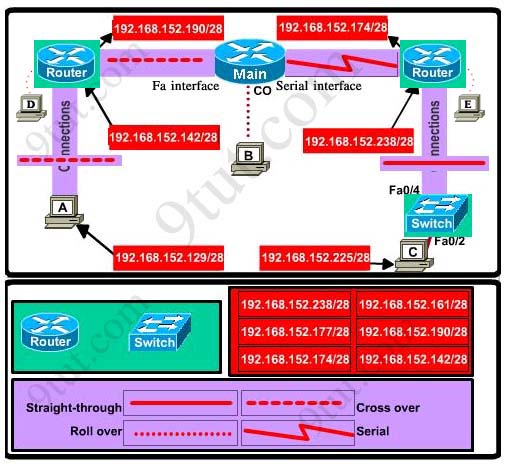
For the device at the bottom-right box, we notice that it has 2 interfaces Fa0/2 and Fa0/4; moreover the link connects the PC on the right with the device on the bottom-right is a straight-through link -> it is a switch
The question stated that this topology contains 3 routers and 1 switch -> two other devices are routers
Place them on appropriate locations as following:

(Host D and host E will be automatically added after placing two routers. Click on them to access neighboring routers)
Specify appropriate connections between these devices:
+ The router on the left is connected with the Main router through FastEthernet interfaces: use a crossover cable
+ The router on the right is connected with the Main router through Serial interfaces: use a serial cable
+ The router on the right and the Switch: use a straight-through cable
+ The router on the left and the computer: use a crossover cable
(To remember which type of cable you should use, follow these tips:
- To connect two serial interfaces of 2 routers we use serial cable
– To specify when we use crossover cable or straight-through cable, we should remember:
Group 1: Router, Host, Server
Group 2: Hub, Switch
One device in group 1 + One device in group 2: use straight-through cable
Two devices in the same group: use crossover cable
For example: we use straight-through cable to connect switch to router, switch to host, hub to host, hub to server… and we use crossover cable to connect switch to switch, switch to hub, router to router, host to host… )

Assign appropriate IP addresses for interfaces:
From Main router, use show running-config command:
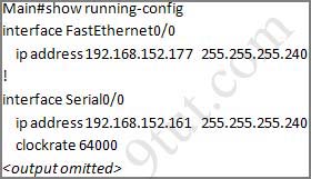
(Notice that you may see different IP addresses in the real CCNA exam, the ones shown above are just used for demonstration)
From the output we learned that the ip address of Fa0/0 interface of the Main router is 192.168.152.177/28. This address belongs to a subnetwork which has:
Increment: 16 (/28 = 255.255.255.240 or 1111 1111.1111 1111.1111 1111.1111 0000)
Network address: 192.168.152.176 (because 176 = 16 * 11 and 176 < 177)
Broadcast address: 192.168.152.191 (because 191 = 176 + 16 – 1)
And we can pick up an ip address from the list that belongs to this subnetwork: 192.168.152.190 and assign it to the Fa0/0 interface the router on the left
Use the same method for interface Serial0/0 with an ip address of 192.168.152.161
Increment: 16
Network address: 192.168.152.160 (because 160 = 16 * 10 and 160 < 161)
Broadcast address: 192.168.152.175 (because 176 = 160 + 16 – 1)
-> and we choose 192.168.152.174 for Serial0/0 interface of the router on the right
Interface Fa0/1 of the router on the left
IP (of the computer on the left) : 192.168.152.129/28
Increment: 16
Network address: 192.168.152.128 (because 128 = 16 * 8 and 128 < 129)
Broadcast address: 192.168.152.143 (because 143 = 128 + 16 – 1)
-> we choose 192.168.152.142 from the list
Interface Fa0/0 of the router on the right
IP (of the computer on the left) : 192.168.152.225/28
Increment: 16
Network address: 192.168.152.224 (because 224 = 16 * 14 and 224 < 225)
Broadcast address: 192.168.152.239 (because 239 = 224 + 16 – 1)
-> we choose 192.168.152.238 from the list
Let’s have a look at the picture below to summarize
Configure two routers on the left and right with these commands:
Router1 = router on the left
Assign appropriate IP addresses to Fa0/0 & Fa0/1 interfaces:
Router1>enable
Router1#configure terminal
Router1(config)#interface fa0/0
Router1(config-if)#ip address 192.168.152.190 255.255.255.240
Router1(config-if)#no shutdown
Router1(config-if)#interface fa0/1
Router1(config-if)#ip address 192.168.152.142 255.255.255.240
Router1(config-if)#no shutdown
Set passwords (configure on two routers)
+ Console password:
Router1(config-if)#exit
Router1(config)#line console 0
Router1(config-line)#password consolepw
Router1(config-line)#login
Router1(config-line)#exit
+ Telnet password:
Router1(config)#line vty 0 4
Router1(config-line)#password telnetpw
Router1(config-line)#login
Router1(config-line)#exit
+ Privilege mode password:
Router1(config)#enable password privpw
Save the configuration:
Router1(config)#exit
Router1#copy running-config startup-config
Configure IP addresses of Router2 (router on the right)
Router2>enable
Router2#configure terminal
Router2(config)#interface fa0/0
Router2(config-if)#ip address 192.168.152.238 255.255.255.240
Router2(config-if)#no shutdown
Router2(config-if)#interface serial0/0
Router2(config-if)#ip address 192.168.152.174 255.255.255.240
Router2(config-if)#no shutdown
and set console, telnet and privilege mode passwords for Router2 as we did for Router1, remember to save the configuration when you finished
Other lab-sims on this site:


Bcoz 192.168.152.177 is already assigned to the fa0/0 of Main router
am writing on tuesday 13 /03/2012, Advice on which dumps are valid, the sims to expect and timing please
Taking test tomorrow 3/12. Know it is late but i just came upon this site today. Excellent information here. Any chance of getting advice on valid dumps, sims to expect? (harryhood92@gmail.com)
@chaudary
better look again for the fa0/0 ip address of the Main router.
Is CCNA really that easy?
Some of the SIMs on here need to be taken with a pinch of salt and you need to look at the actual question. Indeed, the IP address assigned to the Main router in the downloaded SIM are different to that of the question (Fa0/0 = .178, and s0/0 = .172). So, based on the SIM – you could indeed choose either address .177 OR .190 for fa0/0 on Router1, and you could equally choose address .161 OR .174 of s0/0 on Router2.
The Question itself actually says the the address of the interface on the Main Router are fa0/0 = .177, and s0/0 = .161. That being the case, neither of those addresses would be available.
In this question, would you set the enable secret password or just the enable password as shown in the example??
@katie – that’s a good question and one I was wondering. There is another question in the LAB SIMs at the end (NAT 1) that indicates set the “secret” password, so I guess if they just say password, they just mean “enable password”, but its a tricky one. I have come across test questions that have it either way, so its quite confusing.
Dear all, I have a basic doubt. When do we use #login and #no login? I suddenly got confused.
wen i read the book it said #no login throughout.. and i see #login here
i got an ip addr like this 192.168.152.178 for fa0/0 and 192.168.152.172 for s0/0 in main router, what ip address can i choose for the fa0/o and s0/0 for left and right side of the router
then another doubt, u explained in above sim like this format:
Increment: 16 (/28 = 255.255.255.240 or 1111 1111.1111 1111.1111 1111.1111 0000)
Network address: 192.168.152.176 (because 176 = 16 * 11 and 176 < 177)
Broadcast address: 192.168.152.191 (because 191 = 176 + 16 – 1)
And we can pick up an ip address from the list that belongs to this subnetwork: 192.168.152.190 and assign it to the Fa0/0 interface the router on the left u said like this.
what my doubt is how u picked up this ip adrr 192.168.152.190 then y u didn't pick up this 192.168.152.177 addr explain briefly please i cannot understand dude this is also under come from 176 to 191 subnet
please any one help me dude…. iam to write exam this month end please..update soon friends
@ anon, when we use the login command it means that a password is required at logon. the no login command doesn’t mean we are not allowed to login but we can just login without ant password required, so its a huge security breach.
One major problem that can occur is that hnegibors or other people nearby can horn into your network and steal bandwidth (happened to me) and thus make your network work harder and make it slower (doing more work to handle the heavier load!)Get a password on there so’s every device on your network has to know the password to sign in and use your router! Toot sweet!VA:F [1.9.12_1141](from 0 votes)
Hi..I have downloaded the Implementation SIM and when i am trying 2 log into Router 1 & Router 2..Its askiing for a password on both routers..Can anyone please help me with the password..i tried cisco but no go!!!!
Regards,
Narendra
narendra.varma106@gmail.com
I figured it out myself..A console password consolepw was already set and entering the same gave me the access on both the routers!!!
5/14/2012- Has anyone recently seen this ? in the CCNA, taking my exam real soon.
how to apply IP for router and switch with PC? I don’t understand ?I use to provide IP with VLSM but I am not do like this .why we do not apply for different class A, B, C?
hi everybody
Note: “Because routes are not being added to the configurations, you will not be able to ping through the internetwork.”
Does this mean I can not in final ping between PC s?
@Sara, Correct, no ping testing required, just ensure the correct config is implemented
@ AlantheAussie
thanx
I am sorry if this is a stupid question, but why do you use the router on the left and the switch on the right? I know the router directly to the right is used because of the serial connection but if you put the router all the way to the right and the switch on the left, is it wrong?
it is wrong because u have been given a type of cable that has been used between the PC and the device. remember group one + a device in group two use a straight through cable
@taking exam 2morow :-s
any last advises …
@Jim
The “ip addresses” give that one away. The only ip you ould assign on a switch(being layer 2) would be a management ip. not interface ip addresses
RE : For Router on the left of the Main, I want to know you did not choose the ip address 192.168.152.177 since it also belongs to the subnet 192.168.152.176 – 192.168.152.191 as it seems to be a correct ip address to that Router.
I can see why you got confused as i did too, in the packet tracer sim the ip address is not the same as in the answer to the question. In packet tracer the IP is 192.168.152.178 no .177
Thanks
What is the probability that this sim will appear in the exam?
in the packet tracer do you need to use a clockrate so main router and right router can connect ??
On the CCNA, do you need to configure the clock rate? The serial interface on the Main router does not show a clock rate in the Packet Tracer sim.
Hello all,
just got lost. On the left side of Main Router…why we can’t pick a switch instead of router?
When you start this Sim and you do know IP addresses how you know that router is needed but not a switch?
Thanks
Mistake in writing…DO NOT know IP addresses
layer13, because at the right bottom side of the picture we see that host C is conneted with straight-through cabel to the unknown device… so we know that PC’s connet with s-t cabels to switches and hubs… and as we know from the task “This topology contains 3 routers and 1 switch. Complete the topology.”, so we drag in other 2 free positions 2 routers(top left and top rigth sides)…
layer13, and ip addresses are easily discovered from Main router using “show running-config” command…
@layer13: because only a router has an interface named fa0/0.
Switches start with interface fa0/1
hey …
how can i view all the .vce files . i have a player but its only a trial version which allow only 5 questions. Please help me on this
nawab.ansh@gmail.com
thanks :)
Attention from 9tut (Please help me to b clear about the issue )
ballor @ bakh March 8th, 2011
Hi, i have a question
where did these numbers come from the 11 10 8 and 12
192.168.152.176 (because 176 = 16 * 11 and 176 < 177)
192.168.152.160 (because 160 = 16 * 10 and 160 < 161)
192.168.152.128 (because 128 = 16 * 8 and 128 < 129)
192.168.152.224 (because 224 = 16 * 14 and 224 < 225)
thank you
—
The subnet range is 16 from the given /28 which equals 1111 0000 in binary or 255.255.255.240. The 16 is from borrowing 4 bits (hence the 4 zeroes) and thus 2^4 equals 16.
So the valid subnets are all multiples of 16.
192.168.152.0 – subnet 1
192.168.152.16 – subnet 2
192.168.152.32 – subnet 3 and so forth
192.168.152.48
192.168.152.64
192.168.152.80
192.168.152.96
192.168.152.112
192.168.152.128
192.168.152.144
192.168.152.160
192.168.152.176
192.168.152.192
192.168.152.208
192.168.152.224
192.168.152.240
192.168.152.255 (counting from zero…)
The 11 10 8 and 12 are just multiples of 16 to find what subnet the given IP's fit in. Clear as mud?
Hence I am not clear about the numbers 11 10 8 and 12. how we are multiplying these numbers with 16 ? I Understood 16 is our block size but how we r getting these numbers to multipy to get rang ???
please help…
Can’t i get help someone about the above issue ? !!
@jamshed
if its just abt how to get those numbers (11,10,8,14) then you take the number on the fourth octet divide by the block size of which u already knw (16)
i.e 176/16=11
160/16=10
128/16=8
224/16=14
If thats now wat u wanted to knw then please, kindly rephrase the question
in this sim
Is we want to ping from left pc to right pc …………..it is not pinging that’s why i am asking?
Folks,
With trial version, Iam unable to practice much as it is allowing only 5 Questions for an exam
Can some one plese share full version download link of VCE designer?
Please send me the link to: pradeep.6174@gmail.com
Many Thanks,
Prad
It’s Clear
Thank you Ropam..
i have one doubt friends.why didn’t choose switch on the leftside instead of router?.
The config terminal command has been disabled for the HQ router. The router does not require any configuration.
where is Hq router in lab?
As in the question there should be 3 routers in this topology
(This topology contains 3 routers and 1 switch. Complete the topology.)
plz help…while doing static routing …i got an error like inconsistsnt address and mask…ip route 172.168.25.0 255.255.0.0 10.0.0.2
@manoj
You are forgetting about the 3rd octet in the ip address. So the subnet mask should be 255.255.255.0
Any takers on this question?
What program are you guys using to download this simulation. I believe normal clicking to download would not work.
Do I only get packet tracer through Cisco Academy.
hi guys i am going to give CCNA exam and want to know about lab question, could u suggest me which lab is important please.
my e-mail- nileshdubey90@gmail.com
Anyone see this question on a test recently?
I don’t get the addressing between the LEFT ROUTER and MAIN ROUTER. Why is it 190/28?
*********************************************
Main Router: FastEthernet0/0 192.168.152.178/28
*********************************************
This IP range is between 176 and 190. Here’s why:
192.168.152.176 ………………….. Network Address (divisible by 16)
192.168.152.177 ………………….. 1st usable IP (which is also in the choices)
192.168.152.178 ………………….. Main Router’s Fa0/0 IP Address
.
.
.
192.168.152.188 ………………….. Last usable IP
192.168.152.189 ………………….. Broadcast Address
192.168.152.190 ………………….. Next Network Address (divisible by 16)
My answer is 177/28 from the choices. Why am I wrong? Please someone explain this to me. :(