
Frame Relay – GNS3 Lab
In this article we will create a Frame Relay in GNS3 to learn how to configure Frame-Relay.
Note: If you need to revise your Frame Relay knowledge, we recommend you to read our Frame Relay tutorial first.
First we create 4 routers and link them as follows:

IOS used in this lab: c2600-bin-mz.123-6f.bin
Configure IP addresses
First we will assign IP addresses for all relevant interfaces. Notice that R1 will be Frame-Relay switch in this lab so its interfaces don’t need IP addresses.
On R0:
R0#configure terminal
R0(config)#interface s0/0
R0(config-if)#ip address 192.168.1.1 255.255.255.0
R0(config-if)#no shutdown
On R2:
R2#configure terminal
R2(config)#interface s0/0
R2(config-if)#ip address 192.168.1.2 255.255.255.0
R2(config-if)#no shutdown
On R3:
R3#configure terminal
R3(config)#interface s0/0
R3(config-if)#ip address 192.168.1.3 255.255.255.0
R3(config-if)#no shutdown
Configure Frame-Relay (using Inverse ARP)
To configure Frame-Relay on R0, R2 and R3 we need to enable Frame-Relay encapsulation and specify a type of LMI (ansi – in this case). Notice that Inverse ARP is enabled by default on Cisco routers so we don’t need to type anything to activate it.
R0,R2,R3(config)#interface s0/0
R0,R2,R3(config-if)#encapsulation frame-relay
R0,R2,R3(config-if)#frame-relay lmi-type ansi
Configure R1 as a Frame-Relay switch
In this lab R1 will be configured as a Frame-relay switch so no IP address is required.
Turn on Frame-Relay switching feature on R1:
R1(config)#frame-relay switching
On each interface we must specify how the frame will be proceeded. In practical, the Frame-Relay switch (R1) is placed at the ISP side so its interfaces should be set to DCE.
R1(config)# interface s0/0
R1(config-if)#encapsulation frame-relay
R1(config-if)#frame-relay lmi-type ansi
R1(config-if)#frame-relay intf-type dce //This command specifies the interface to handle LMI like a Frame Relay DCE device.
R1(config-if)#clock rate 64000
R1(config-if)#frame-relay route 102 interface Serial0/1 201 (will be explained later)
R1(config-if)#frame-relay route 103 interface Serial0/2 301
The command frame-relay route 102 interface Serial0/1 201 means frame-relay traffic come to R1 which has a DLCI of 102 will be sent to interface Serial0/1 with a DLCI of 201.
Note: Data link connection identifiers (DLCIs) are numbers that refer to paths through the Frame Relay network. They are only locally significant.
Continue configuring s0/1 & s0/2 interfaces (same as s0/0)
R1(config)# interface s0/1
R1(config-if)#encapsulation frame-relay
R1(config-if)#frame-relay lmi-type ansi
R1(config-if)#frame-relay intf-type dce
R1(config-if)#clock rate 64000
R1(config-if)#frame-relay route 201 interface Serial0/0 102
R1(config)# interface s0/2
R1(config-if)#encapsulation frame-relay
R1(config-if)#frame-relay lmi-type ansi
R1(config-if)#frame-relay intf-type dce
R1(config-if)#clock rate 64000
R1(config-if)#frame-relay route 301 interface Serial0/0 103
Use the show frame-relay map command to display the current map entries for static and dynamic routes
R0#show frame-relay map
By default, Cisco uses Inverse ARP to map remote IP address of the PVC with the DLCI of the local interface as we can see here. From the output above we learn that DLCI 102 is set on Serial0/0 of R0 and mapped with 192.168.1.2. The status of this connection is “dynamic” and “active”, which means it is operating correctly.
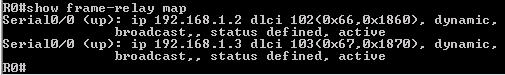
The outputs of this command on other routers are shown below:
![]()
![]()
Notice that you will only see the “map” at two ends. If we issue this command on Frame-Relay switch (R1 is this case) it will show nothing.
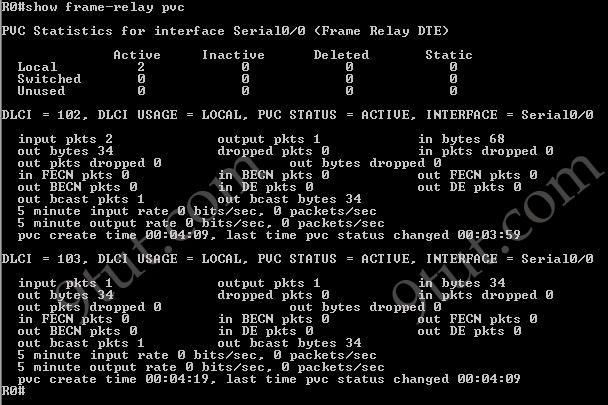
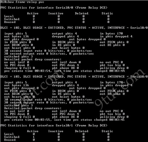
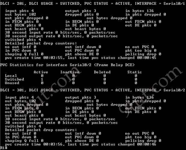
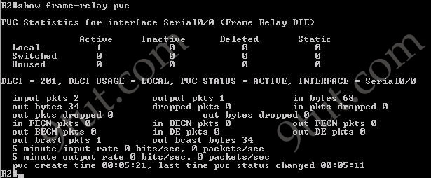
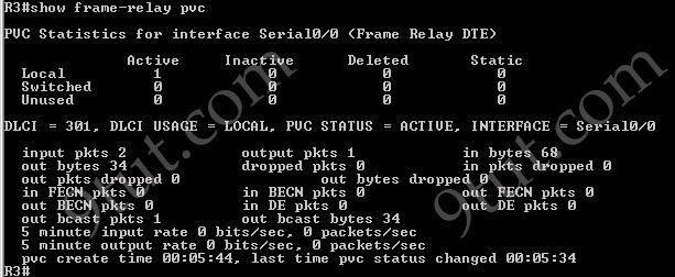
The show frame-relay pvc command is used to display the status of all configured connections, traffic statistics, BECN and FECN packets received by the router.
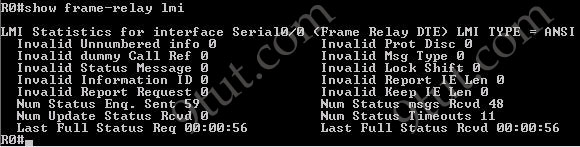
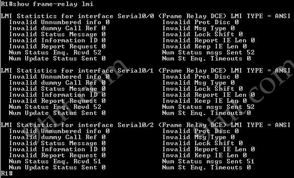
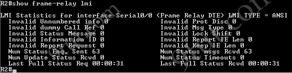
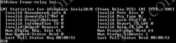
Use the show frame-relay lmi to display LMI traffic statistics (including LMI type, status messages sent and invalid LMI messages)
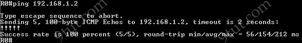
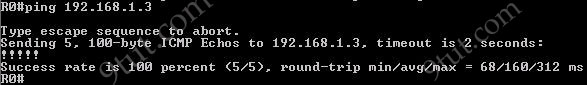
Pings from R0 to R2 & R3 are successful.
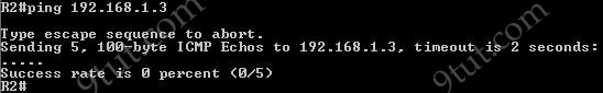
However ping from R2 to R3 is unsuccessful. It means that customers cannot see each other. This is because the split horizon rule: “A router never sends information about a route back in same direction which is original information came”. To overcome this problem we can configure subinterfaces on R0.


What routers and switches are you using
hiya, would you be able to upload topology for this gns lab pls?
In this lab we don’t need a router! We use a router as a Frame-Relay switch!
The version of the routers are mentioned above (c2600-bin-mz.123-6f.bin)
@andrus: This lab is simple so I hope you will create the topology by yourself to grasp the concept!
Hi,
I have noticed that the config for making a fram switch is wrong it should be the following
no ip address
! As this is the fram switch it does not need a IP
no ip directed-broadcast
encapsulation frame-relay
! To make it speak Frame-Relay
logging event subif-link-status
logging event dlci-status-change
! To log changes to dlci or sub interface
no shutdown
clock rate 56000
! Define the clock rate of DCE
no frame-relay inverse-arp
frame-relay lmi-type ansi
! To change the LMI Type this command is not need if you use the
! the LMI type cisco or you can ues q933a
!
frame-relay intf-type dce
frame-relay route 201 interface Serial0/0 102
! Route commands to connect dlci 201 on this port to interface serial 0/0 on dlci 102
and in globle config mode
#frame-relay switching
“To overcome this problem we can configure subinterfaces on R0″
or disable split horizon
R1(config-if)#no ip split-horizon
or…..
R2(config-if)#frame-relay map ip 192.168.1.3 201 broadcast
R3(config-if)#frame-relay map ip 192.168.1.2 301 broadcast
Note: Broadcast key word is for using routing protocols
*R0(config-if)#no ip split-horizon
I agree with anonymous and his commands are accurate, after going to other sources such as cisco.com.
when I am typing R1(config-if)#frame-relay route 201 int s0/0 102
it is showing “route command not allowed between two DTE interfaces”
i think you have done some wrong cmds
verify=R1(config-if)#frame-relay intf-type dce
instead of =R1(config-if)#encapsulation lmi-type dce
topology file for GNS3
http://ge.tt/8GwqKb8?c
what router we required in frame relay for configure switch…????
@Lokendra: As I said in this post, all the routers use the c2600-bin-mz.123-6f.bin image.
this router isn’t configure as a switch………
i hope you did configure it as a switch then, at least do one thing yourself.
R1(config)# interface s0/0
R1(config-if)#encapsulation frame-relay
R1(config-if)#encapsulation lmi-type ansi
R1(config-if)#encapsulation lmi-type dce
R1(config-if)#clock rate 64000
R1(config-if)#frame-relay route 102 interface Serial0/1 201 (will be explained later)
R1(config-if)#frame-relay route 103 interface Serial0/2 301
encapsulation lmi-type ansi or encapsulation lmi-type dce is not accepted by my ios…
im using c2600-bin-mz.123-18.image…any advise?
yeah thats wrong
R1(config-if)#frame-relay lmi-type ansi
R1(config-if)#frame-relay intf-type dce
m practising for frame relay ,m using 2620 router available in packet tracer ,but there is no such command “frame-relay switching” in it ,pls help me out.
use GNS3.. do not rely on Packet tracer.
@abhishek @Adnan
I assume you’re trying to configure the frame relay switch. Configuring the frame relay switch is not part of the CCNA. You only need to configure the endpoints. So that command is not in Packet Tracer because Packet Tracer is designed for CCNA-Level material.
If you insert the cloud object in Packet Tracer, you can configure the cloud to be your Frame Relay switch. You won’t get the experience of configuring the switch manually, but again, frame relay switch configuration is not part of the CCNA syllabus. Only configuring the endpoints is.
Change the configuration for the FR switch. It’s incorrect.
Yes, configuring a frame-relay switch is not apart of the CCNA objectives, however… Getting frame-relay to work is a part of the objectives. There’s a lot of material that cover Frame-Relay switching and GNS3 is one of the best ways to do it. Unfortantly GNS3 lacks switching, so configuring a router to do the switching is a part of the studies – indirectly.
can any one tell ,which router is shown in the diagram ? plz
Configure a routing protocol on all routers first if you want “show frame-relay map” to work or for that matter ping.
R?(config)# ip routing
R?(config)#router eigrp 1
R?(config-router)#network 192.168.1.0
R?(config-router)#network 192.168.2.0 (if you have more than one)
First we will assign IP addresses for all relevant interfaces. Notice that R1 will be Frame-Relay switch in this lab so its interfaces don’t need IP addresses.
On R0:
R0#configure terminal
R0(config)#interface s0/0
R0(config-if)#ip address 192.168.1.1 255.255.255.0
R0(config-if)#no shutdown
On R2:
R2#configure terminal
R2(config)#interface s0/0
R2(config-if)#ip address 192.168.1.2 255.255.255.0
R2(config-if)#no shutdown
On R3:
R3#configure terminal
R3(config)#interface s0/0
R3(config-if)#ip address 192.168.1.3 255.255.255.0
R3(config-if)#no shutdown
Configure Frame-Relay
To configure Frame-Relay on R0, R2 and R3 we need to enable Frame-Relay encapsulation and specify a type of LMI (ansi – in this case)
R0,R2,R3(config)#interface s0/0
R0,R2,R3(config-if)#encapsulation frame-relay
R0,R2,R3(config-if)#frame-relay lmi-type ansi
Configure R1 as a Frame-Relay switch
In this lab R1 will be configured as a Frame-relay switch so no IP address is required.
Turn on Frame-Relay switching feature on R1:
R1(config)#frame-relay switching
On each interface we must specify how the frame will be proceeded. In practical, the Frame-Relay switch (R1) is placed at the ISP side so its interfaces should be set to DCE.
R1(config)# interface s0/0
R1(config-if)#encapsulation frame-relay
R1(config-if)#frame-relay lmi-type ansi
R1(config-if)#frame-relay intf-type dce
R1(config-if)#clock rate 64000
R1(config-if)#frame-relay route 102 interface Serial0/1 201 (will be explained later)
R1(config-if)#frame-relay route 103 interface Serial0/2 301
The command frame-relay route 102 interface Serial0/1 201 means frame-relay traffic come to R1 which has a DLCI of 102 will be sent to interface Serial0/1 with a DLCI of 201.
Note: Data link connection identifiers (DLCIs) are numbers that refer to paths through the Frame Relay network. They are only locally significant.
Continue configuring s0/1 & s0/2 interfaces (same as s0/0)
R1(config)# interface s0/1
R1(config-if)#encapsulation frame-relay
R1(config-if)#frame-relay lmi-type ansi
R1(config-if)#frame-relay intf-type dce
R1(config-if)#clock rate 64000
R1(config-if)#frame-relay route 201 interface Serial0/0 102
R1(config)# interface s0/2
R1(config-if)#encapsulation frame-relay
R1(config-if)#frame-relay lmi-type ansi
R1(config-if)#frame-relay intf-type dce
R1(config-if)#clock rate 64000
R1(config-if)#frame-relay route 301 interface Serial0/0 103
I update these commands
R1(config-if)#frame-relay lmi-type ansi
R1(config-if)#frame-relay intf-type dce
ON ROUTER R1:
instead of
R1(config-if)#encapsulation lmi-type ansi
it should be R1(config-if)#framerelay lmi-type ansi
If in CCNA we have to configure only an endpoints, and we use GNS3, just to simplify the whole idea of FR, we can use FrameRelay Switch that is available instead of making one from a router. Then configure the endpoints. FR with router on the middle confused me for good few hours, I had to read from few different sources to truly understand the whole concept. I gained bit more knowledge but frustration was the price :)
Who can show how to overcome split-horizont issue using sub-interfaces?
Please, write a configuration on R1.
I don’t exactly understand what frame-relay swith does:
Is it router? If it is a router where split-horizont issue appeared?
Because in this case we have usual router which interfaces connected to the three usual routers – R0,R2,R3. Am I right?
host R1
interface l0
ip address 192.168.1.1 255.255.255.255
interface s0/0
encapsulation frame-relay
frame-relay lmi-type ansi
ip address 123.0.0.1 255.255.255.0
no shutdown
host R2
interface l0
ip address 192.168.2.2 255.255.255.255
interface s0/0
encapsulation frame-relay
frame-relay lmi-type ansi
frame-relay map ip 123.0.0.3 201 broadcast
ip address 123.0.0.2 255.255.255.0
no shutdown
host R3
interface l0
ip address 192.168.3.3 255.255.255.255
interface s0/0
encapsulation frame-relay
frame-relay lmi-type ansi
frame-relay map ip 123.0.0.2 301 broadcast
ip address 123.0.0.3 255.255.255.0
no shutdown
host FRSW
frame-relay switching
interface s 1/1
encapsulation frame-relay
frame-relay lmi-type ansi
frame-relay intf-type dce
clock rate 64000
frame-relay route 102 interface Serial 1/2 201
frame-relay route 103 interface Serial 1/3 301
no shut
interface s 1/2
encapsulation frame-relay
frame-relay lmi-type ansi
frame-relay intf-type dce
clock rate 64000
frame-relay route 201 interface Serial 1/1 102
no shut
interface s 1/3
encapsulation frame-relay
frame-relay lmi-type ansi
frame-relay intf-type dce
clock rate 64000
frame-relay route 301 interface Serial 1/1 103
no shut
exit
router ospf 1
network 123.0.0.0 0.0.0.255 area 1
network 192.168.0.0 0.0.255.255 area 1
ip ospf priority 0
well linda here is the web address address , they have a wealth of knowledge , mention gary fetlen told you to ring
encapsulation frame-relay
frame-relay lmi-type ansi
when I am typing R1(config-if)#frame-relay route 201 int s0/0 102
it is showing “route command not allowed between two DTE interfaces”
if any one suggest plz help
The ping is not working not due to split-horizon problem but because of no PVC between R2 and R3, both interfaces are in the same subnet so no need for routing protocol.
~jeevan
Did you set on each interface DCE type?
The command should be on each interface: frame-relay intf-type dce
i really wonder how u people have this much of patience to clear all doubts thank u
u wasted my time, i didnt need your help!@!
NOTE**** Cisco Packet Tracer DOES NOT support Frame Relay on the Routers!!! Bummer :(. But, you can user the Cloud simulator to practice Frame Relay. Sorry ya’ll. :)
very informative discussion….
thx to allllllllllllllllllll
Can any one help me get the ios c2600-bin-mz.123-6f.bin? if possible email it it or how to get that at fazemcc@hotmail.com.. Thanks
Im sorry what routing protocol is being used in the above sim? Ive done everything above using the added info from comments regarding the frame-relay lmi-type ansi correction.
But when i write show frame-relay map all i get is a empty line
I’ve seen some mistakes here as well, especially configuring R1 as the DCE. encapsulation lmi-type dce doesnt work. you have to you frame-relay lmi-type, then hit enter, then type dce
i want to ask something.How to configure ospf and RIP v2?
Why we don’t have “frame-relay interface-dlci ” set on R0,R2,R3 serial interfaces ?
koopotang :
by default, once we configure command encapsulation frame-relay on main interface ( not sub interface ) its will form mapping automatically,so we dont need config that command.
why didn’t we define a dlci number to r0
dear 9tut can i perform this practical over packet tracer
@anil rana: I am not sure but maybe you can do this lab in Packet Tracer.
sir
this type of configuration doesn’t work with packet tracer
kindly share the latest version packet tracer which can perform gns3 configuration
dear 9tut team kindly give us your mail id which can discuss the matter
my email id is anilrana00@gmail.com
@anil rana: You can send us to this email: support@9tut.com
regarding getting R2 and R3 working I found that making R0 a subinterface didn’t make things work. My GNS3 is working fine. I don’t see a solution posted here. I agree that there needs to be a pvc between R2 and R3 which really makes the lab a Frame-relay mesh network.
Can somebody write down correction on this lab I am new in Frame Rely and i am confused i would like to learn this. Please can somebody explain me this lab??????Please can somebody send me working GNS3 lab.
mattlessons@gmail.com