
CCNA – WAN 2
Here you will find answers to WAN Questions – Part 2
If you are not sure about Frame Relay, please read my Frame Relay tutorial.
Question 1
Users have been complaining that their Frame Relay connection to the corporate site is very slow. The network administrator suspects that the link is overloaded. Based on the partial output of the Router#show frame relay pvc command shown in the graphic, which output value indicates to the local router that traffic sent to the corporate site is experiencing congestion?

A. DLCI=100
B. last time PVC status changed 00:25:40
C. in BECN packets 192
D. in FECN packets 147
E. in DF packets 0
Answer: C
Explanation
First we should grasp the concept of BECN & FECN through an example:
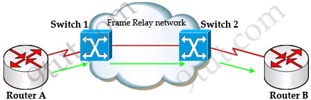
Suppose Router A wants to send data to Router B through a Frame Relay network. If the network is congested, Switch 1 (a DCE device) will set the FECN bit value of that frame to 1, indicating that frame experienced congestion in the path from source to destination. This frame is forwarded to Switch 2 and to Router B (with the FECN bit = 1).
Switch 1 knows that the network is congesting so it also sends frames back to Router A with BECN bit set to 1 to inform that path through the network is congested.
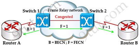
In general, BECN is used on frames traveling away from the congested area to warn source devices that congestion has occurred on that path while FECN is used to alert receiving devices if the frame experiences congestion.
BECN also informs the transmitting devices to slow down the traffic a bit until the network returns to normal state.
The question asks “which output value indicates to the local router that traffic sent to the corporate site is experiencing congestion” which means it asks about the returned parameter which indicates congestion -> BECN.
Question 2
When troubleshooting a Frame Relay connection, what is the first step when performing a loopback test?
A. Set the encapsulation of the interface to HDLC.
B. Place the CSU/DSU in local-loop mode.
C. Enable local-loop mode on the DCE Frame Relay router.
D. Verify that the encapsulation is set to Frame Relay.
Answer: A
Explanation
The first thing when performing a loopback test on a Frame Relay connection is to reconfigure the encapsulation of the interface to HDLC protocol instead of Frame Relay protocol. The main reason is Frame Relay requires a pair of DCE/DTE which cannot be used in a loopback test.
For more information about steps of trouble shooting Frame Relay, please read: http://www.cisco.com/en/US/tech/tk713/tk237/technologies_tech_note09186a008014f8a7.shtml#topic20
For your information, below is a paragraph quoted from the above link:
“Serial0 is down, line protocol is down”
This output means you have a problem with the cable, channel service unit/data service unit (CSU/DSU), or the serial line. You need to troubleshoot the problem with a loopback test. To do a loopback test, follow the steps below:
1. Set the serial line encapsulation to HDLC and keepalive to 10 seconds. To do so, issue the commands encapsulation hdlc and keepalive 10 under the serial interface.
2. Place the CSU/DSU or modem in local loop mode. If the line protocol comes up when the CSU, DSU or modem is in local loopback mode (indicated by a “line protocol is up (looped)” message), it suggests that the problem is occurring beyond the local CSU/DSU. If the status line does not change states, there is possibly a problem in the router, connecting cable, CSU/DSU or modem. In most cases, the problem is with the CSU/DSU or modem.
3. Ping your own IP address with the CSU/DSU or modem looped. There should not be any misses. An extended ping of 0×0000 is helpful in resolving line problems since a T1 or E1 derives clock from data and requires a transition every 8 bits. B8ZS ensures that. A heavy zero data pattern helps to determine if the transitions are appropriately forced on the trunk. A heavy ones pattern is used to appropriately simulate a high zero load in case there is a pair of data inverters in the path. The alternating pattern (0×5555) represents a “typical” data pattern. If your pings fail or if you get cyclic redundancy check (CRC) errors, a bit error rate tester (BERT) with an appropriate analyzer from the telco is needed.
4. When you are finished testing, make sure you return the encapsulation to Frame Relay.
Question 3
What occurs on a Frame Relay network when the CIR is exceeded?
A. All TCP traffic is marked discard eligible.
B. All UDP traffic is marked discard eligible and a BECN is sent.
C. All TCP traffic is marked discard eligible and a BECN is sent.
D. All traffic exceeding the CIR is marked discard eligible.
Answer: D
Explanation
Committed information rate (CIR): The minimum guaranteed data transfer rate agreed to by the Frame Relay switch. Frames that are sent in excess of the CIR are marked as discard eligible (DE) which means they can be dropped if the congestion occurs within the Frame Relay network.
Note: In the Frame Relay frame format, there is a bit called Discard eligible (DE) bit that is used to identify frames that are first to be dropped when the CIR is exceeded.
Question 4
What are two characteristics of Frame Relay point-to-point subinterfaces? (Choose two)
A. They create split-horizon issues.
B. They require a unique subnet within a routing domain.
C. They emulate leased lines.
D. They are ideal for full-mesh topologies.
E. They require the use of NBMA options when using OSPF.
Answer: B C
Question 5
The output of the show frame-relay pvc command shows ”PVC STATUS=INACTIVE”. What does this mean?
A. The PVC is configured correctly and is operating normally,but no data packets have been detected for more than five minutes.
B. The PVC is configured correctly, is operating normally and is no longer actively seeking the address the remote route,
C. The PVC is configured correctly, is operating normally and is waiting for interesting to trigger a call to the remote router.
D. The PVC is configured correctly on the local switch, but there is a problem on the remote end of the PVC.
E. The PVC is not configured on the switch.
Answer: D
Explanation
The PVC STATUS displays the status of the PVC. The DCE device creates and sends the report to the DTE devices. There are 4 statuses:
+ ACTIVE: the PVC is operational and can transmit data
+ INACTIVE: the connection from the local router to the switch is working, but the connection to the remote router is not available
+ DELETED: the PVC is not present and no LMI information is being received from the Frame Relay switch
+ STATIC: the Local Management Interface (LMI) mechanism on the interface is disabled (by using the “no keepalive” command). This status is rarely seen so it is ignored in some books.
Question 6
Which encapsulation type is a Frame Relay encapsulation type that is supported by Cisco routers?
A. Q933-A Annex A
B. IETF
C. ANSI Annex D
D. HDLC
Answer: B
Explanation
Cisco supports two Frame Relay encapsulation types: the Cisco encapsulation and the IETF Frame Relay encapsulation, which is in conformance with RFC 1490 and RFC 2427. The former is often used to connect two Cisco routers while the latter is used to connect a Cisco router to a non-Cisco router. You can test with your Cisco router when typing the command Router(config-if)#encapsulation frame-relay ? on a WAN link. Below is the output of this command (notice Cisco is the default encapsulation so it is not listed here, just press Enter to use it).
![]()
Note: Three LMI options are supported by Cisco routers are ansi, Cisco, and Q933a. They represent the ANSI Annex D, Cisco, and ITU Q933-A (Annex A) LMI types, respectively.
HDLC is a WAN protocol same as Frame-Relay and PPP so it is not a Frame Relay encapsulation type.
Question 7
Router A is unable to reach Router B. Both routers are running ios version 12.0. After reviewing the command output and graphic, what is the most likely cause of the problem?
A. incorrect bandwidth configuration
B. incorrect LMI configuration
C. incorrect map statement
D. incorrect IP address
Answer: C
Explanation
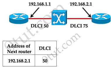
With this topology and the DLCI, we can only think of “incorrect map statement”. From the topology we can deduce traffic with a DLCI of 75 will be sent to 192.168.2.1 but the text below wrongly shows “DLCI 50″ for the next router 192.168.2.1 -> C is correct.


Hi CLS, my understanding is that NBMA is for frame relay multipoint
Can someone please help me understand Question 7 above..?
Can someone please help me understand Question 7 above..
@ Karthik K
The DILCI is a layer 2 address used by Frame Relay. When looking at the topology diagram, we see that the DILCI is 75 on the interface with IP 192.168.2.1. However, when looking at the command output the DILCI is 50 instead of 75, meaning the map statement is incorrect.
for more info on frame-relay map statement,
I’m confused in question 7, in Left routers perspective the table should be correct because the DLCI is local to the left router and it is mapped to the ip address of right router.
Q7 is wrong. Frame relay DLCI is only local sygnificant so mapping is good. From router on the left perspective the “tunnel” to 192.168.2.1 is that one with dlci 50. He doesn’t know what dlci numer is configured on right router. I think the right answer is B.
My mistake, since frame-relay map shows the inverse arp, q 7 must be wrong
Yes, I think the answer in Q7 must be “incorrect LMI configuration”
What does IOS version has to do?
Question 7 is wrong in my opinion – I agree with answer B – Per Cisco routers at each end of a Frame Relay virtual circuit must always use the same LMI type
Q7.
“Starting with Cisco IOS software release 11.2, the default LMI autosense feature detects the LMI type supported by the directly connected Frame Relay switch. Based on the LMI status messages it receives from the Frame Relay switch, the router automatically configures its interface with the supported LMI type acknowledged by the Frame Relay switch. ”
Source: CCNA Exploration
So B is not the answer. There’s nothing wrong with the DLCI for this question. Can someone shed light on this please??? @xallax
Q7.
If we all assume that IP address 192.168.1.1 and DLCI 50 is assigned to the router on the left, and IP address of 192.168.2.1 and DCLI 75 is assigned to the router on the right than the output is correct. So we can assume that the map statement is correct. However the LMI can be hardcoded #frame-relay lmi-type (ansi | cisco |q933a) which leads me to believe the LMI configuration is wrong. Configuring the LMI is optional after IOS 11.2 but since it was a multiple choice that is the most reasonable choice. Honestly, arguments can be made about all choices. We can’t see the pvc config on both routers or the LMI statistics. We don’t know if the router on the right was configured correctly. Is the pvc dynamic or statically assigned. Maybe it is configured dynamically and someone turned off inverse-arp… wait who would do that? I have no clue but so much troubleshooting can come from this partial output.
So 9tut can you please help us understand question and designated answer for Q7, thanks!
@xallax
can you help me in these two Questions
1-What is the advantage of using a multipoint interface instead of point-to-point subinterfaces when configuring a Frame Relay hub in a hub-and-spoke topology?
A- It avoids split-horizon issues with distance vector routing protocols.
B- IP addresses can be conserved if VLSM is not being used for subnetting.
C- A multipoint interface offers greater security compared to point-to-point subinterface configurations.
D- The multiple IP network addresses required for a multipoint interface provide greater addressing flexibility over point-to-point configurations.
is it true the correct answer is B
2-An administrator is configuring a router that will act as the hub in a Frame Relay hub-and-spoke topology. What is the advantage of using point-to-point subinterfaces instead of a multipoint interface on this router?
A- It avoids split-horizon issues with distance vector routing protocols.
B-Only one IP network address needs to be used to communicate with all the spoke devices.
C- Point-to-point subinterfaces offer greater security compared to a multipoint interface configuration.
D- Only a single physical interface is needed with point-to-point subinterfaces, whereas a multipoint interface logically combines multiple physical interfaces.
is it true the correct answer is A
I agree on you CCENT, but now I know the relation of the version to the problem. I still think B is the answer because obviously in the map table, map statement is correct.
@smart86
first question
a. it is actually more susceptible to split-horizon issues as routing updates come and go out the same interface.
c. receiving more traffic on the same interface doesnt mean it is safer. false
d. “multiple ip addresses”? it uses just 1 IP address.
b. is correct by ruling the others out.
if vlsm isnt used for subnetting then each p2p link would cost you an entire class a/b/c network. if the interface is set as multipoint then you are wasting just 1 classful network for the router links
2nd question
split-horizon is on by default on subinterface no matter if they’re multipoint or p2p (it is off by default on interfaces!). if every pvc has its own subinterface then there shouldn’t split horizon issues. i see A as correct
Guys, dont you think the right answer of Q7 is D incorrect IP address, cuase the two routers are not in the same subnet??
@bill
we can’t say they arent in the same subnet unless subnetmask is provided.
@xallax
what’s your take on Q7?
looking at that image you can easily figure out that the output is being shown on the left router and it should display info regarding the router on the right: the IP address of the connected interface and the DLCI.
the dlci should be 75
C is correct.
A) cant tell by the output provided. false
B) can’t tell either, says nothing about the encapsulation or keepalive or anything else LMI-related. false
D) the IP address is indeed 192.168.2.1 BUT this is not a problem (remember that the task at hand is to figure out the problem)
For question 7 I think the correct answer is D cause considering the C class of the subnet and its default mask /24, the routers are not in the same subnet.
As for DLCI mapping it seems to be ok and LMI should be ok also cause we have the mapping of the other PVC end.
Q7:
The DLCI table of the left router looks correct to me, since next-hop add is respective to local DLCI.
Since the info given is correct, a likely cause could be incorrect LMI configuration (not shown) e.g. LMI type mis-match. Remember, question is asking for LIKELY cause.
Actually this qn is very similar to the following question:
http://www.aiotestking.com/cisco/2012/04/what-is-the-most-likely-cause-of-the-problem-6/
Again i find the answer in the above link is wrong too (config looks correct to me)
Perhaps 9tut would like to comment?
Pls, can somebody send me the latest dumps, i have exam this month,
my email is asholet98@hotmail.com
Thanks
@xallax
Which command allows you to verify the encapsulation type (CISCO or IETF) for a frame relay link?
A.show framerelay map
B.show framerelay lmi
C.show inter serial
D.show framerelay pvc
what is the correct answer: A or B
I think B is correct in because show frame-relay lmi the type of frame relay is mention
Router#sh frame-relay lmi
LMI Statistics for interface Serial0 (Frame Relay DTE)
LMI TYPE = CISCO
Invalid Unnumbered info 0 Invalid Prot Disc 0
but in sh frame-relay map it dose not mention
RouterB#show frame-relay map
Serial0 (up): ipx 20.0007.7842.3575 dlci 16(0×10,0×400),
dynamic, broadcast,, status defined, active
Serial0 (up): ip 172.16.20.1 dlci 16(0×10,0×400),
dynamic, broadcast,, status defined, active
Serial1 (up): ipx 40.0007.7842.153a dlci 17(0×11,0×410),
also what make A correct answer is that itef and cisco is form of frame-relay encapsulation
while lmi type are cisco ansi q933a
so what is the correct answer?
i hop my explanation is correrct
Q7 answer is D.
they are on different networks >.<
@xallax
I know that I am asking too much but I hope you answering me soon
@9tut
i want to ask that CHAP is based on 3-way handshaking or 2-way handshaking ??
plzz respond me with details
@kushal arora: CHAP is based on 3-way handshaking. Maybe you should google or read some CCNA books for more detail. I can’t write it here because it’s too long.
@smart86
i’d say “show interface serial” is correct as it displays L2 details such as encapsulation
@xallax
thank you very much an I really appreciate your help in explaining any questions I posted
@xallax
as I read from cisco website:
http://www.cisco.com/en/US/docs/internetworking/troubleshooting/guide/tr1918.html#wp1020680
they mention: When connecting Cisco devices with non-Cisco devices, you must use IETF encapsulation on both devices. Check the encapsulation type on the Cisco device with the show frame-relay map exec command.
now i am confusing between show interface serial & show frame-relay map I know that show interface serial will show LMI type as well as frame relay encapsulation
@smart86
it says specifically for a frame-relay link so the “show frame-relay map” command could be the only accepted answer.
“show int serial” would show the encapsulation for all serial links, not just the frame-relay ones
@9tut – thanks very much for the clear and concise explanation!
As a possible improvement, maybe it would be helpful if you could list the 3 main show commands ( show frame-relay map/pvc/lmi ) with screens of outputs and what kind of information can be learned from each ( DLCI number , encaps type, status, etc).
I know all the information is in the tutorial + can be seen from the practice questions but it would be good to have it all in one place.
Giving my CCNA in 2 weeks, will definitely donate after that. Keep up the good work! :D
@smart86
I would agree with xallax, show frame-relay map is a better answer because it is specific to FR.
show interface serial would list all serial links even the ones not using FR specifically.
Both commands would give you the encapsulation type but the first show command would be more acceptable I guess.
@ CCNAman i support your ans for Q7. the right ans is D. because even if the frame-relay map statement is correct. both interfaces are on different subnet they cant communicate.
@ xallax and 9tut think about this point and update us.
thanks
@9tut
kool man !! thnx
@sniffer
me also in confusion on Q 7.
@ kushal dont b confuse. i tested on packet tracer and upon my conclusion i will choice D.
@sniffer
let d 9tut answer this qustion..i think he will give ans. with explanation
@xallax
A network administrator needs to configure a serial link between the main office and a remote location. The router at the remote office is a non-Cisco router. How should the network administrator configure the serial interface of the main office router to make the connection?
A-Main(config)# interface serial 0/0
Main(config-if)#ip address 172.16.1.1 255.255.255.252
Main(config-if)#encapsulation ietf
Main(config-if)# no shut
B-Main(config)# interface serial 0/0
Main(config-if)#ip address 172.16.1.1 255.255.255.252
Main(config-if)# no shut
C-Main(config)# interface serial 0/0
Main(config-if)#ip address 172.16.1.1 255.255.255.252
Main(config-if)#encapsulation PPP
Main(config-if)# no shut
D-Main(config)# interface serial 0/0
Main(config-if)#ip address 172.16.1.1 255.255.255.252
Main(config-if)#encapsulation frame-relay
Main(config-if)# authentication chap
Main(config-if)# no shut
in the dumps the answer is (C) but I think the correct answer is (A) because at the remote office there is a non-Cisco router as I mention up{When connecting Cisco devices with non-Cisco devices, you must use IETF encapsulation on both devices}
please can you help me in this question?
@smart86
hdlc is the default encapsulation on cisco routers. when connecting non-cisco routers you should use PPP.
option C is indeed correct
@ smart i also think C is the correct ans because the encapsulation cammand is not correct. its either (encapsulation frame-relay ietf ) for routers from different vendors or encaps ppp. note hdlc is the default for cisco routers.
@Smart86 the correct answer for showing frame-relay encapsulation type is show interface serial because show frame-relay map is only showing details about IP to DLCI mapping :
Router#show frame-relay map
Serial0/0 (up): ip 192.168.1.2 dlci 102(0×66,0×1860), dynamic,
broadcast,, status defined, active
@smart
i think that the wright answer is A because encapsulation between a router cisco and a non-cisco router is IETF.
@9tut
can you explain about Q 7 please . there are many students including me confused about answer C . we ill appreciate it.
@imran: Yes, Q7 is a bit difficult to understand but it will be long to explain. As I can say, you should learn more about “Global DLCI”, which is used in this question. A good document can be found here:
http://www.routeralley.com/ra/docs/frame_relay.pdf
Q7
I don’t see how Global DLCIs effect this question at all. According to that PDF a Global DLCI is when you use the same DLCI on different routers to point to the same place. Like in the PDF example of having both Detroit and Houston use the locally significant 102 DLCI to point to Chicago.
I don’t think Q7 is hard to explain at all:
A: Bandwidth is provided as best effort so they don’t need to be the same
B: Because the question specifically states ver12 we assume LMI was autonegotiated.
C: The map statement is correct because it has the target IP with the local DLCI
So that leaves D. Point to Point frame relay needs to be in the same network.
Even in the Global DLCI part of that PDF all the routers at in the same network.
@xallax
Hi! Clarification regarding your answer to smart 86.
@smart86
first question
a. it is actually more susceptible to split-horizon issues as routing updates come and go out the same interface
In Multipoint we will create sub interfaces so there must not be split-horizon Issues right?
Please advice Many thanks!
@xallax
Sorry got confused. You are correct.
@9tut
Note: Three LMI options are supported by Cisco routers are ansi, Cisco, and Q933a. They represent the ANSI Annex D, Cisco, and ITU Q933-A (Annex A) LMI types, respectively.
HDLC is a WAN protocol same as Frame-Relay and PPP so it is not a Frame Relay encapsulation type.
A network administrator needs to configure a serial link between the main office and a remote location. The router at the remote office is a non-Cisco router. How should the network administrator configure the serial interface of the main office router to make the connection?
Can you pls explain why answer C is correct.
Thanks
@notbuyigit I think your answer is correct about Q7.
@ Everyone!
The answer to Q7 is wrong..
There is no more need for any one to explain as to why the answer to q7 is right.
I did a lab on this with packet tracer, and when I put the IP address of 192.168.2.1 on the the serial interface of the other router, there was no connectivity, i.e, no ICMP reply, but when I changed the IP add the communication was there.
So I think the option ‘D’ incorrect IP address is the right option because they are not on the same subnet with the default /24 mask.
My understanding as to why my answer is right.
1.When writing Frame map statements, you always map the local DLCI to the remote IP address, there fore, the Router A(one on the left) will use DLCI 50 to reach Router B (The router that has the IP add 2.1). Therefore the frame maps are right(if this had the ption to choose two correct answers then it would have been c&d because you need to write a new statement indicating the new IP address).
2.Itis so ridiculously obvious the routers are not in the same subnet.
When using Frame Relay this matters. If you just plug the routers with serial cable and use PPP or HDLC, the pings will go out and connectivity will be established. However the WAN protocols such as OSPF and EIGRP won’t work, because for the neighbor Adjacency to be established, the remote router needs to be on the same subnet as the sending router.
Hope this clears the doubts.