
CCNA – WAN 2
Here you will find answers to WAN Questions – Part 2
If you are not sure about Frame Relay, please read my Frame Relay tutorial.
Question 1
Users have been complaining that their Frame Relay connection to the corporate site is very slow. The network administrator suspects that the link is overloaded. Based on the partial output of the Router#show frame relay pvc command shown in the graphic, which output value indicates to the local router that traffic sent to the corporate site is experiencing congestion?

A. DLCI=100
B. last time PVC status changed 00:25:40
C. in BECN packets 192
D. in FECN packets 147
E. in DF packets 0
Answer: C
Explanation
First we should grasp the concept of BECN & FECN through an example:
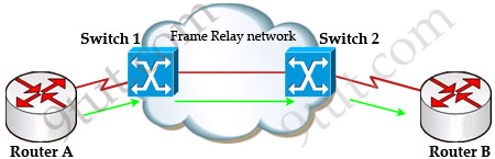
Suppose Router A wants to send data to Router B through a Frame Relay network. If the network is congested, Switch 1 (a DCE device) will set the FECN bit value of that frame to 1, indicating that frame experienced congestion in the path from source to destination. This frame is forwarded to Switch 2 and to Router B (with the FECN bit = 1).
Switch 1 knows that the network is congesting so it also sends frames back to Router A with BECN bit set to 1 to inform that path through the network is congested.
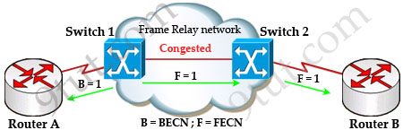
In general, BECN is used on frames traveling away from the congested area to warn source devices that congestion has occurred on that path while FECN is used to alert receiving devices if the frame experiences congestion.
BECN also informs the transmitting devices to slow down the traffic a bit until the network returns to normal state.
The question asks “which output value indicates to the local router that traffic sent to the corporate site is experiencing congestion” which means it asks about the returned parameter which indicates congestion -> BECN.
Question 2
When troubleshooting a Frame Relay connection, what is the first step when performing a loopback test?
A. Set the encapsulation of the interface to HDLC.
B. Place the CSU/DSU in local-loop mode.
C. Enable local-loop mode on the DCE Frame Relay router.
D. Verify that the encapsulation is set to Frame Relay.
Answer: A
Explanation
The first thing when performing a loopback test on a Frame Relay connection is to reconfigure the encapsulation of the interface to HDLC protocol instead of Frame Relay protocol. The main reason is Frame Relay requires a pair of DCE/DTE which cannot be used in a loopback test.
For more information about steps of trouble shooting Frame Relay, please read: http://www.cisco.com/en/US/tech/tk713/tk237/technologies_tech_note09186a008014f8a7.shtml#topic20
For your information, below is a paragraph quoted from the above link:
“Serial0 is down, line protocol is down”
This output means you have a problem with the cable, channel service unit/data service unit (CSU/DSU), or the serial line. You need to troubleshoot the problem with a loopback test. To do a loopback test, follow the steps below:
1. Set the serial line encapsulation to HDLC and keepalive to 10 seconds. To do so, issue the commands encapsulation hdlc and keepalive 10 under the serial interface.
2. Place the CSU/DSU or modem in local loop mode. If the line protocol comes up when the CSU, DSU or modem is in local loopback mode (indicated by a “line protocol is up (looped)” message), it suggests that the problem is occurring beyond the local CSU/DSU. If the status line does not change states, there is possibly a problem in the router, connecting cable, CSU/DSU or modem. In most cases, the problem is with the CSU/DSU or modem.
3. Ping your own IP address with the CSU/DSU or modem looped. There should not be any misses. An extended ping of 0×0000 is helpful in resolving line problems since a T1 or E1 derives clock from data and requires a transition every 8 bits. B8ZS ensures that. A heavy zero data pattern helps to determine if the transitions are appropriately forced on the trunk. A heavy ones pattern is used to appropriately simulate a high zero load in case there is a pair of data inverters in the path. The alternating pattern (0×5555) represents a “typical” data pattern. If your pings fail or if you get cyclic redundancy check (CRC) errors, a bit error rate tester (BERT) with an appropriate analyzer from the telco is needed.
4. When you are finished testing, make sure you return the encapsulation to Frame Relay.
Question 3
What occurs on a Frame Relay network when the CIR is exceeded?
A. All TCP traffic is marked discard eligible.
B. All UDP traffic is marked discard eligible and a BECN is sent.
C. All TCP traffic is marked discard eligible and a BECN is sent.
D. All traffic exceeding the CIR is marked discard eligible.
Answer: D
Explanation
Committed information rate (CIR): The minimum guaranteed data transfer rate agreed to by the Frame Relay switch. Frames that are sent in excess of the CIR are marked as discard eligible (DE) which means they can be dropped if the congestion occurs within the Frame Relay network.
Note: In the Frame Relay frame format, there is a bit called Discard eligible (DE) bit that is used to identify frames that are first to be dropped when the CIR is exceeded.
Question 4
What are two characteristics of Frame Relay point-to-point subinterfaces? (Choose two)
A. They create split-horizon issues.
B. They require a unique subnet within a routing domain.
C. They emulate leased lines.
D. They are ideal for full-mesh topologies.
E. They require the use of NBMA options when using OSPF.
Answer: B C
Question 5
The output of the show frame-relay pvc command shows ”PVC STATUS=INACTIVE”. What does this mean?
A. The PVC is configured correctly and is operating normally,but no data packets have been detected for more than five minutes.
B. The PVC is configured correctly, is operating normally and is no longer actively seeking the address the remote route,
C. The PVC is configured correctly, is operating normally and is waiting for interesting to trigger a call to the remote router.
D. The PVC is configured correctly on the local switch, but there is a problem on the remote end of the PVC.
E. The PVC is not configured on the switch.
Answer: D
Explanation
The PVC STATUS displays the status of the PVC. The DCE device creates and sends the report to the DTE devices. There are 4 statuses:
+ ACTIVE: the PVC is operational and can transmit data
+ INACTIVE: the connection from the local router to the switch is working, but the connection to the remote router is not available
+ DELETED: the PVC is not present and no LMI information is being received from the Frame Relay switch
+ STATIC: the Local Management Interface (LMI) mechanism on the interface is disabled (by using the “no keepalive” command). This status is rarely seen so it is ignored in some books.
Question 6
Which encapsulation type is a Frame Relay encapsulation type that is supported by Cisco routers?
A. Q933-A Annex A
B. IETF
C. ANSI Annex D
D. HDLC
Answer: B
Explanation
Cisco supports two Frame Relay encapsulation types: the Cisco encapsulation and the IETF Frame Relay encapsulation, which is in conformance with RFC 1490 and RFC 2427. The former is often used to connect two Cisco routers while the latter is used to connect a Cisco router to a non-Cisco router. You can test with your Cisco router when typing the command Router(config-if)#encapsulation frame-relay ? on a WAN link. Below is the output of this command (notice Cisco is the default encapsulation so it is not listed here, just press Enter to use it).
![]()
Note: Three LMI options are supported by Cisco routers are ansi, Cisco, and Q933a. They represent the ANSI Annex D, Cisco, and ITU Q933-A (Annex A) LMI types, respectively.
HDLC is a WAN protocol same as Frame-Relay and PPP so it is not a Frame Relay encapsulation type.
Question 7
Router A is unable to reach Router B. Both routers are running ios version 12.0. After reviewing the command output and graphic, what is the most likely cause of the problem?
A. incorrect bandwidth configuration
B. incorrect LMI configuration
C. incorrect map statement
D. incorrect IP address
Answer: C
Explanation
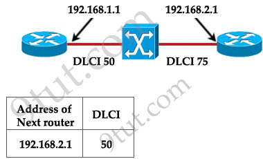
With this topology and the DLCI, we can only think of “incorrect map statement”. From the topology we can deduce traffic with a DLCI of 75 will be sent to 192.168.2.1 but the text below wrongly shows “DLCI 50″ for the next router 192.168.2.1 -> C is correct.


can anybody explain right answer of Q. 7 ???
@kart
agree wid u man !!! but dint understand ur 2nd point
As far as my understanding about frame relay question no.7 if we had two choices then options(C and D) correct answer but have to choose one option that is C (incorrect map statement) BECAUSE statement is incorrect due to incorrect ip.
Option C (incorrect map statement) covers the incorrect ip address.
q7– we are talking about a wan — why should a wan be on same subnet? — these addresses are private addresses — wan is not a private network?? — I am not sure about this question
q7– the more I look at it — the problem is with the private addressing —
Any network that connects beyond LAN is called WAN. If that is your company network, they will use private addresses to communicate. WAN Public IP.
If the router on the right had 192.168.1.2, and if the map statement was written as shown in the exhibit, then it would have been an incorrect map statement, or if there was no option that highlighted the phenomenon of incorrect IP address then it would have been the incorrect map statement because amongst the options shown that would have been the best option.
I am using Todd Lamle’s CCNA exam prep book, check the chapter on Frame-Relay even he has represented the frame statements same as shown in this exhibit, except they the two routers on the same subnet.
I am surprised that some commenteers here don’t think for frame-relay connection to be established the routers between which the PVC is formed don’t require the layer 3 addresses to be in the same address space!!
Even if there was a possiblity of having data connectivity between the routers in a PVC in different subnets, then it would be pointless, because there is no way OSPF can run in that situation, because one of the core requirement of OSPF is that the neighboring routers need to be in the same subnet for an adjacency to be formed.
Don’t take my word for it, try this out on your own in packet tracer.
@geedub
As far as I understand, you don’t need public address for a WAN connectivity, if we did, then would have run out of public addresses a hundred times by now. Since because we are not involving the internet , it is just a connection established between two offices in different geographical areas,the data is just needs to shared between the offices not anyone else.
If you are using VPN to linkup the offices then public IP is needed but that’s another story.
One of the features of Frame-Relay is, they emulate leased lines, i.e, its as if you had a private line between the two offices.
Review the chapter on OSPF then you’ll understand why they need to be on the same subnet.
Q7
I was initially stumped by this question and even suspected that wording/diagram is wrong. On close look, there is nothing wrong with the map statement. The next-hop IP addr must map to the LOCAL DLCI, which is correct as shown.
The answer is right before your eyes – the two IPs are not in the same subnet! Because Frame Relay WAN is Layer 2, the point-to-point IPs must be in the same subnet. Simple as that.
Correct answer should be D, not C. Hope 9tut can update the answer.
Q7
I also believe that D is the correct answer for 2 reasons:
1) As they have said, the 2 interfaces aren’t on the same subnet.
2) C can’t be the correct answer because that’s how we exactly map networks on frame relay
ex.
frame-relay map ip 192.168.2.1 50 broadcast
Syntax goes
frame-relay map ip (destination IP) (“source” DLCI)
Q7
I agree with you guys, answer “D” is the correct one,
The IP addresses have to be on the same subnet, the DLCI actually simulates a Point to Point connection, so the addresses have to be on the same subnet.
9tut please update your answer thanks!
@ 9TUT and everyone!
I tried the Q7 setup on GNS3 (Which uses real Cisco router image to run the routers for learning purposes) I used 1700 series image which I had in my lab router.
I first did the setup with different ip addresses and put the map statements accordingly. (I mapped the local DLCI to the remote router’s IP address) it didn’t work.
Then I changed the ip address of one of the routers so that they were both on the 192.168.1.0/24 subnet, then POOF it worked!!!!
9TUT please change the answer for Q7 as being incorrect IP address.
@Kart: Q7, in the topology we can’t identify which is RouterA. If it is the router on the left then the answer can’t be “incorrect IP address”. Otherwise, D will be the correct answer.
@9TUT thank you for your reply.
I see that there is no specificity as to which router is Router A or Router B.
There are some clues available upon a closer look.
If you see in the exhibit, the map statement has been shown as Address of the next router(192.168.2.1) and the local DLCI(50). Since the syntax is correct (R1(config-if)#frame map ip 192.168.2.1 50 broadcast) we can rule out the incorrect map statement option.
I also feel it is quite obvious that the router on the left is router A because ‘A’ is alphabetically first, and when counting since it is counted from left to right the router on the left is Router A.
There is also another clue, in the question they say “Router A cannot reach Router B” therefore since the problem is first noticed on Router A they have shown the configuration of Router A, and also the DLCI 50 is put close to the left side router, and because of DLCI’s local significance rule I believe they are referencing the left router as being Router A.
Kindly clarify further.
@ 9TUT
Further more I feel its a trick question, the configuration information on the left router has been shown deliberately so that the candidates suspect that something is wrong with the map statement, when the problem is with the IP addresses.
I feel this is a good example for the real world because we’re always looking for something complicated as being wrong in a complex configuration, when sometimes it can be as simple as this.
@Kart: If the router on the left is Router A then the “Address of next router” is 192.168.2.1 is correct and the answer can’t be “incorrect IP address”.
the answer to question 7 is ” incorrect lmi configuration” why
((ref ccna accessing the wan page 148- 149))
lmi is a keepalive mechanism that provide info about frame relay connection between DTE and frame relay switch and it is sent every 10s and the switch does not care about encapsulation but end devices do. switch care about lmi only.
it is important when manually configuring lmi to configure the keepalive interval to prevent status exchange btw the ends from timing out.
This status exchange mesg determine the status of pvc connection and a large mismatch can cause the switch to declare the router dead.
@ Desk IT There is no reference to LMI configuration in Q7 whatsoever(They have not specified the left router as using Cisco LMI and the right router using ANSI or Q933a, that would be too obvious), there fore LMI can’t be the issue.
@ 9TUT if what you say about incorrect IP address option being incorrect is the true,
Then the answer can’t be incorrect map statement either, because how is it possible to base the map statement as being incorrect on something that is incorrect in itself??
What I mean is, if the “Syntax” was incorrect then we could have said that it is the map statement, because in that case regardless of the IP addresses if the syntax was wrong there could not be any kind of connection establishment.
However as you can see the syntax is indeed correct (the Local DLCI and the address of the next router), Just like how we refer in the networking world to OSI model, for connectivity issues, “if you don’t have layer 2 connectivity then there is no way layer 3 connectivity can be established.”
Same way Even though Frame-relay is a layer 2 protocol I am referencing to the steps, I feel the assignment of the right IP addresses to the respective interfaces is STEP 2 then creating Frame maps is STEP 3, if someone is ‘off’ in their second step there is no reason to blame Step 3 for being wrong, when it was in step 2 they tripped.
@9TUT
There exists yet another interpretation of this question, you are suggesting that the right answer should be “incorrect map statement” because they are referencing to the router on the left for incorrect configuration? well even then the incorrect IP address option can be upheld.
Assuming that the configuration of the right router is correct and complete, the IP addresses was intended to be on the 192.168.2.0/24 subnet, then we can conclude that the network admin assigned the wrong IP address to the left router, instead of putting 192.168.2.2 or 3/24 or something else, he put 192.168.1.1 by accident??
This proves beyond a shadow of a doubt that the issue is the wrong IP address not the map statement.
After all CCNA modules and a lot a study I finally understeand BECN & FECN. Very good explanation on Q1 @9tut.
@ 9tut but the topology was meant to route so i stick to my ans
Becos Ip wont be the issue this is not pt-pt
@ 9tut
there are network sim in the cisco press that configures frame network wth diff ips
i checkd this to be sure
@ 9tut
there are network sim in the cisco press that configures frame network wth diff ips
i checkd this to be sure
tmr is my ccna any latest
@deskIT you need to understand the concepts properly, you clearly have not understood the concepts of IP addresses and Frame-Relay. Please review page no.474 and 475 in ICND 2 book from Cisco press by Odom. I feel you’re clearly not ready for the exam, please review the key concepts.
Remember that just studying these dumps can’t allow you to pass.
And please don’t continue to publish your bogus comments it is sure to confuse new comers.
agree with U (Q.7)
q7 the c “C. incorrect map statement
” answer in not correct because of the following :
the map statement should be used in point to multipoint method
like
frane-relay map ip 192.168.2.1 50
but also in point to multipoint method all the routers must be in the same subnet which is not happening here
So i think the answer is D
q7–I am still confused == 9tut explain this better
@geedub: Please read my explanation (in comments).
your little box — address of next router and dlci number — still does not tell me if the dlci number is local — and I feel that it is local — so the router this is from is on the left or A and the dlci number for A is 50 —
q7— there is very little information to decide the correct answer and you are saying that you have ruled out A, B, and D– so the only possible is C??? so the little box is not showing us a mapping statement — so we can assume that there is an incorrect mapping statement== if we see your little box as a mapping statement then C is a wrong answer — so it is the little box that is confusing people –
q7— It is the picture that is confusing people — dlci 50 and 75 dont point to any particular location where the arrows in the picture do point to the address — so a dlci of 75 should be assigned to router A or the one on the left and your box shows that it is reading dlci 50?!
q7– so if you associate the dlci of 75 with router A then the mapping statement is wrong if you see the little box as a mapping of address to dlci 50 instead of 75
q7– you are saying that your picture shows us that the dlci 75 is associated or learned from router A — so your picture is confusing and router B learns dlci 75 is on A
Q7
The explanation given makes no sense. From the thoery the explanation given is exactly wrong. From router A the mapping to 192.168.2.1 (which must obviously be from the router on the left) should be associated to the local DLCI 50.
I do not know which answer is correct but I would say the mapping would seem correct, if no mapping, lmi has mapped it correctly, therefore it must be D.
Maybe you should just remove this question!
@deskIT
pls don’t confuse everybody. you’re just doing a copy-paste comment.
the answer is D. even on a simple setup of two PCs connected together but on a different subnet, it just won’t work.
I have an issue with question 2. HDLC is not an encapsulation type it is a protocol so how can this answer A be right?
@Mex, when you have the frame-relay as the WAN protocol on a serial interface, you can’t ping your own serial interface without having a frame map for that address, so in order to do a loopback test(ping the local interface within the router itself), since HDLC is the default encap type on serial interfaces, setting it to default encap type will enable the admin to verify if the interface is ok.
Hope it helps.
q7
scored 1000/1000. had this question on the exam. unless this was one of the non-scoring questions, the answer was D: incorrect ip address.
Q7
Correct Answer is (( incorrect ip address ))
because THIS Command
frame-relay map ip 192.168.2.1 50 broadcast
never accept
so iam not important where router A or B
frist not accept command
I dont understand why you’re all arguing about the map OR ip settings. There both correct imho. I assume R1 is the left one and thus its using the right DLCI to reach 192.168.2.1. As far as we’re concerned, maybe the routers are part or about to take part in a of a huge frame-relay multi-point network – since we dont know the netmask.
Even though.. I now agree that IP-adressing is the correct answer, since the question states the most likely cause.
@Q7
Check this link same answer with 9tut…i think C is correct
http://www.aiotestking.com/cisco/2012/04/what-is-the-most-likely-cause-of-the-problem-5/
It has become necessary to configure an existing serial interface to accept a second Frame Relay virtual circuit. Which of the following procedures are required to accomplish this task? (Choose three.)
A. Remove the IP address from the physical interface.
B. Encapsulate the physical interface with multipoint PPP.
C. Create the virtual interfaces with the interface command.
D. Configure each subinterface with its own IP address.
E. Disable split horizon to prevent routing loops between the subinterface networks.
F. Configure static Frame Relay map entries for each subinterface network.
Answer to different dump
BCD
ACD
DEF
Which of the three answer is true?
@Newbie!
ACD
right Itachi
Guys, about question 7, why do you think that the answer should be D? Maybe the subnet mask is /23, we can’t be sure that both sides aren’t in the same subnet.
*I meant /22, my bad ;)
I assume that this is a logical point-to-point connection and the mapping statement is correct but the IP address belongs on different IP subnet so in this case the correct answer should be D.